Chevrolet Trax: Stop lamps malfunction
Diagnostic Instructions
- Perform the Diagnostic System Check - Vehicle prior to using this diagnostic procedure.
- Review Strategy Based Diagnosis for an overview of the diagnostic approach.
- Diagnostic Procedure Instructions provides an overview of each diagnostic category.
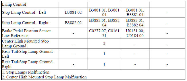
Diagnostic Fault Information
.jpg)
Circuit/System Description
The brake pedal position (BPP) sensor is used to sense the action of the driver application of the brake pedal.
The BPP sensor provides an analog voltage signal that will increase as the brake pedal is applied. The body control module (BCM) provides a low reference signal and a 5-volt reference voltage to the BPP sensor. When the variable signal reaches a voltage threshold indicating the brakes have been applied, the BCM will apply battery voltage to the left and right stop lamp control circuits as well as the center high mounted stop lamp (CHMSL) control circuit illuminating the left and right stop lamps and the CHMSL.
Diagnostic Aids
When testing at the stop lamp bulb socket, make sure all measurements and test lamp connections are in the correct terminal location and do not come in contact with each other during testing.
Reference Information
Schematic Reference
Exterior Lights Schematics (Encore) , Exterior Lights Schematics (Trax)
Connector End View Reference
WIRING SYSTEMS AND POWER MANAGEMENT - COMPONENT CONNECTOR END VIEWS - INDEX - ENCORE WIRING SYSTEMS AND POWER MANAGEMENT - COMPONENT CONNECTOR END VIEWS - INDEX - TRAX
Description and Operation
Exterior Lighting Systems Description and Operation
Electrical Information Reference
- Circuit Testing
- Connector Repairs Testing for Intermittent Conditions and Poor Connections
- Wiring Repairs
Scan Tool Reference
Control Module References for scan tool information
Circuit/System Verification
- Ignition ON.
- Verify the scan tool Brake Lamps Command parameter changes between Active and Inactive while pressing and releasing the brake pedal.
- If the parameter does not change
Refer to Brake Pedal Position Sensor Malfunction.
- If the parameter changes
- Verify the left brake lamp turns ON and OFF when commanding the Left Rear Brake/Park Lamp ON and OFF with a scan tool.
- If the left brake lamp does not turn ON and OFF
Refer to Stop Lamps Malfunction
- If the left brake lamp turns ON and OFF
- Verify the right brake lamp turns ON and OFF when commanding the Right Rear Brake/Park Lamp ON and OFF with a scan tool.
- If the right brake lamp does not turn ON and OFF
Refer to Stop Lamps Malfunction.
- If the right brake lamp turns ON and OFF
- Verify the center high mounted stop lamp turns ON and OFF when commanding the Center Brake Lamp ON and OFF with a scan tool.
- If the center high mounted stop does not turn ON and OFF
Refer to Center High Mount Stop Lamp Malfunction.
- If the center high mounted stop turns ON and OFF
- All OK.
Circuit/System Testing
Brake Pedal Position Sensor Malfunction
- Ignition OFF, disconnect the harness connector at the B22 Brake Pedal Position Sensor, ignition ON.
- Test for less than 1 V between the appropriate low reference circuit terminal listed below and ground.
- Terminal 2 - with MH8/MHB
- Terminal A - without MH8/MHB
- If 1 V or greater
- Ignition OFF, disconnect the X1 harness connector at the K9 Body Control Module, ignition ON.
- Test for less than 1 V between the low reference circuit and ground.
- If 1 V or greater, repair the short to voltage on the circuit.
- If less than 1 V, replace the K9 Body Control Module.
- If less than 1 V
- Test or re
Stop Lamps Malfunction
- Ignition OFF, exterior lamps OFF, rear hatch latch latched, remove the appropriate E5A Tail/Stop Lamp bulb.
- Test for less than 5 ohms between the ground circuit at the socket terminal and ground.
- If 5 ohms or greater
- Ignition OFF.
- Test for less than 2 ohms in the ground circuit end to end.
- If 2 ohms or greater, repair the open/high resistance in the circuit.
- If less than 2 ohms, repair the open/high resistance in the ground connection.
- If less than 5 ohms
- Connect a test lamp between the control circuit at the socket terminal and ground, ignition ON.
- Verify the test lamp turns ON and OFF when commanding the appropriate Rear Stop Lamp ON and OFF with a scan tool.
- If the test lamp is always OFF
- Ignition OFF, disconnect the appropriate harness connector listed below at the K9 Body Control Module.
- X4 left stop lamp
- X5 right stop lamp
- Test for infinite resistance between the control circuit and ground.
- If less than infinite resistance, repair the short to ground on the circuit.
- If infinite resistance
- Test for less than 2 ohms in the control circuit end to end.
- If 2 ohms or greater, repair the open/high resistance in the circuit.
- If less than 2 ohms, replace the K9 Body Control Module.
- If the test lamp is always ON
- Ignition OFF, disconnect the appropriate harness connector listed below at the K9 Body Control Module, ignition ON.
- X4 left stop lamp
- X5 right stop lamp
- Test for less than 1 V between the control circuit terminal and ground.
- If 1 V or greater, repair the short to voltage on the circuit.
- If less than 1 V, replace the K9 Body Control Module.
- If the test lamp turns ON and OFF
- Test or replace the appropriate E5A Tail/Stop Lamp.
Center High Mount Stop Lamp Malfunction
- Ignition OFF, exterior lamps OFF, rear hatch latch latched, disconnect the harness connector at the E6 Center High Mounted Stop Lamp.
- Test for less than 5 ohms between the ground circuit terminal B and ground.
If 5 ohms or greater
- Ignition OFF.
- Test for less than 2 ohms in the ground circuit end to end.
- If 2 ohms or greater, repair the open/high resistance in the circuit.
- If less than 2 ohms, repair the open/high resistance in the ground connection.
- If less than 5 ohms
- Connect a test lamp between the control circuit terminal A and ground, ignition ON.
- Verify the test lamp turns ON and OFF when commanding the Center Stop Lamp ON and OFF with a scan tool.
- If the test lamp is always OFF
- Ignition OFF, disconnect the X4 harness connector at the K9 Body Control Module.
- Test for infinite resistance between the control circuit and ground.
- If less than infinite resistance, repair the short to ground on the circuit.
- If infinite resistance
- Test for less than 2 ohms in the control circuit end to end.
- If 2 ohms or greater, repair the open/high resistance in the circuit.
- If less than 2 ohms, replace the K9 Body Control Module.
- If the test lamp is always ON
- Ignition OFF, disconnect the X4 harness connector at the K9 Body Control Module, ignition ON.
- Test for less than 1 V between the control circuit terminal and ground.
- If 1 V or greater, repair the short to voltage on the circuit.
- If less than 1 V, replace the K9 Body Control Module
- If the test lamp turns ON and OFF
- Test or replace the E6 Center High Mounted Stop Lamp.
Repair Instructions
Perform the Diagnostic Repair Verification after completing the repair.
- High Mount Stop Lamp Replacement
- Brake Pedal Position Sensor Calibration
- Brake Pedal Position Sensor Replacement
- Stop and Tail Lamp Bulb Replacement (Trax) , Stop and Tail Lamp Bulb Replacement (Encore)
- Control Module References for BCM replacement, programming, and setup
