Chevrolet Trax: Turn signal lamps and/or indicators malfunction
Diagnostic Instructions
- Perform the Diagnostic System Check - Vehicle prior to using this diagnostic procedure.
- Review Strategy Based Diagnosis for an overview of the diagnostic approach.
- Diagnostic Procedure Instructions provides an overview of each diagnostic category
Diagnostic Fault Information
.jpg)
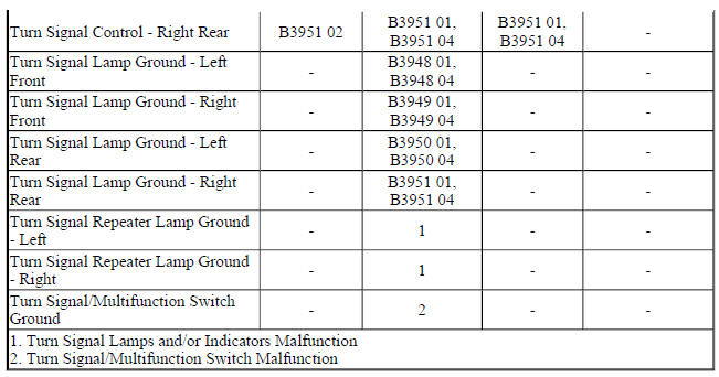
Circuit/System Description
Ground is applied at all times to the turn signal/multifunction switch. The turn signal lamps may only be activated with the ignition switch in the ON or START positions. When the turn signal/multifunction switch is placed in either the turn right or turn left position, ground is applied to the body control module (BCM) through either the right turn or left turn signal switch signal circuit. The BCM responds to the turn signal switch input by applying a pulsating voltage to the front and rear turn signal lamps through there respective control circuits.
When a turn signal request is received by the BCM, a serial data message is sent to the instrument cluster requesting the respective turn signal indicator be pulsed ON and OFF.
Diagnostic Aids
When testing at the turn signal lamp bulb socket, make sure all measurements and test lamp connections are in the correct terminal location and do not come in contact with each other during testing.
Reference Information
Schematic Reference
- Exterior Lights Schematics (Encore) , Exterior Lights Schematics (Trax)
- Body Control System Schematics (Encore) , Body Control System Schematics (Trax)
Connector End View Reference
WIRING SYSTEMS AND POWER MANAGEMENT - COMPONENT CONNECTOR END VIEWS - INDEX - ENCORE WIRING SYSTEMS AND POWER MANAGEMENT - COMPONENT
CONNECTOR END VIEWS - INDEX - TRAX
Description and Operation
Exterior Lighting Systems Description and Operation
Electrical Information Reference
- Circuit Testing
- Connector Repairs
- Testing for Intermittent Conditions and Poor Connections
- Wiring Repairs
Scan Tool Reference
Control Module References for scan tool information
Circuit/System Verification
- Ignition ON.
- Verify the scan tool Right Turn Signal Switch and Left Turn Signal Switch parameters change between Active and Inactive while cycling the turn signal switch between the right and left positions.
- If the parameters do not change
Refer to Turn Signal/Multifunction Switch Malfunction.
- If the parameters change
- Verify the left front turn signal lamps turn ON and OFF while commanding the Left Front Turn Signal Lamp ON and OFF with a scan tool.
- If the left front turn signal lamps do not turn ON and OFF
Refer to Turn Signal Lamps Malfunction.
- If the left front turn signal lamps turn ON and OFF
- Verify the right front turn signal lamps turn ON and OFF while commanding the Right Front Turn Signal Lamp ON and OFF with a scan tool.
- If the right front turn signal lamps do not turn ON and OFF
Refer to Turn Signal Lamps Malfunction
- If the right front turn signal lamps turn ON and OFF
- Verify the left rear turn signal lamps turn ON and OFF while commanding the Left Rear Turn Signal Lamp ON and OFF with a scan tool.
- If the left rear turn signal lamps do not turn ON and OFF
Refer to Turn Signal Lamps Malfunction
- If the left rear turn signal lamps turn ON and OFF
- Verify the right rear turn signal lamps turn ON and OFF while commanding the Right Rear Turn Signal Lamp ON and OFF with a scan tool.
- If the right rear turn signal lamps do not turn ON and OFF
Refer to Turn Signal Lamps Malfunction.
- If the right rear turn signal lamps turn ON and OFF
- Verify the left and right turn signal indicators turn ON and OFF while commanding the All Indicators Test ON and OFF with a scan tool.
- If the left or right turn signal indictors do not turn ON and OFF
Refer to Turn Signal Indicators Malfunction
- If the left and right turn signal indictors turn ON and OFF
- All OK.
Circuit/System Testing
Turn Signal/Multifunction Switch Malfunction
- Ignition OFF, scan tool disconnected, all doors closed, all accessories OFF, disconnect the harness connector at the S78 Turn Signal/Multifunction Switch. It may take up to 2 minutes for all vehicle systems to power down.
- Test for less than 15 ohms between the ground circuit terminal 3 and ground.
If 15 ohms or greater
- Ignition OFF.
- Test for less than 2 ohms in the ground circuit end to end.
- If 2 ohms or greater, repair the open/high resistance in the circuit.
- If less than 2 ohms, repair the open/high resistance in the ground connection.
- If less than 15 ohms
- Ignition ON.
- Verify the scan tool Left Turn Signal Switch parameter is Inactive.
- If not Inactive
- Ignition OFF, disconnect the X3 harness connector at the K9 Body Control Module.
- Test for infinite resistance between the signal circuit terminal 1 and ground.
- If less than infinite resistance, repair the short to ground on the circuit.
- If infinite resistance, replace the K9 Body Control Module.
- If Inactive
- Install a 3 A fused jumper wire between the signal circuit terminal 1 and the ground circuit terminal 3.
- Verify the scan tool Left Turn Signal Switch parameter is Active.
- If not Active
- Ignition OFF, disconnect the X3 harness connector at the K9 Body Control Module, ignition ON.
- Test for less than 1 V between the signal circuit terminal 1 and ground.
- If 1 V or greater, repair the short to voltage on the circuit.
- If less than 1 V
- Test for less than 2 ohms in the signal circuit end to end.
- If 2 ohms or greater, repair the open/high resistance in the circuit.
- If less than 2 ohms, replace the K9 Body Control Module.
- If Active
- Verify the scan tool Right Turn Signal Switch parameter is Inactive.
- If not Inactive
- Ignition OFF, disconnect the X3 harness connector at the K9 Body Control Module.
- Test for infinite resistance between the signal circuit terminal 7 and ground.
- If less than infinite resistance, repair the short to ground on the circuit.
- If infinite resistance, replace the K9 Body Control Module.
- If Inactive
- Install a 3 A fused jumper wire between the signal circuit terminal 7 and the ground circuit terminal 3.
- Verify the scan tool Right Turn Signal Switch parameter is Active.
- If not Active
- Ignition OFF, disconnect the X3 harness connector at the K9 Body Control Module, ignition ON.
- Test for less than 1 V between the signal circuit terminal 7 and ground.
- If 1 V or greater, repair the short to voltage on the circuit.
- If less than 1 V
- Test for less than 2 ohms in the signal circuit end to end.
- If 2 ohms or greater, repair the open/high resistance in the circuit.
- If less than 2 ohms, replace the K9 Body Control Module.
- If Active
- Test or replace the S78 Turn Signal/Multifunction Switch.
Turn Signal Lamps Malfunction
- Ignition OFF, exterior lamps OFF, rear hatch latch latched, disconnect the harness connector at the appropriate E4 Turn Signal Lamp.
- Test for less than 5 ohms between the appropriate ground circuit terminal listed below and ground.
- E4LF Turn Signal Lamp - Left Front socket terminal
- E4RF Turn Signal Lamp - Right Front socket terminal
- E4Y Turn Signal Repeater Lamp - Left terminal 1
- E4Z Turn Signal Repeater Lamp - Right terminal 1
- E4LR Turn Signal Lamp - Left Rear socket terminal
- E4RR Turn Signal Lamp - Right Rear socket terminal
- If 5 ohms or greater
- Ignition OFF.
- Test for less than 2 ohms in the ground circuit end to end.
- If 2 ohms or greater, repair the open/high resistance in the circuit.
- If less than 2 ohms, repair the open/high resistance in the ground connection.
- If less than 5 ohms
- Connect a test lamp between the appropriate control circuit terminal listed below and ground.
- E4LF Turn Signal Lamp - Left Front socket terminal
- E4RF Turn Signal Lamp - Right Front socket terminal
- E4Y Turn Signal Repeater Lamp - Left terminal 2
- E4Z Turn Signal Repeater Lamp - Right terminal 2
- E4LR Turn Signal Lamp - Left Rear socket terminal
- E4RR Turn Signal Lamp - Right Rear socket terminal
- Verify the test lamp turns ON and OFF when commanding the appropriate Turn Signal Lamp ON and OFF with a scan tool.
- If the test lamp is always OFF
- Ignition OFF, disconnect the appropriate harness connector listed below at the K9 Body Control Module.
- X5 left turn signals
- X4 right turn signals
- Test for infinite resistance between the control circuit and ground.
- If less than infinite resistance, repair the short to ground on the circuit.
- If infinite resistance
- Test for less than 2 ohms in the control circuit end to end.
- If 2 ohms or greater, repair the open/high resistance in the circuit.
- If less than 2 ohms, replace the K9 Body Control Module.
- If the test lamp is always ON
- Ignition OFF, disconnect the appropriate harness connector listed below at the K9 Body Control Module, ignition ON.
- X5 left turn signals
- X4 right turn signals
- Test for less than 1 V between the control circuit terminal and ground.
- If 1 V or greater, repair the short to voltage on the circuit.
- If less than 1 V, replace the K9 Body Control Module.
- If the test lamp turns ON and OFF
- Test or replace the appropriate E4 Turn Signal Lamp.
Turn Signal Indicators Malfunction
- Ignition ON.
- Verify the left and right turn signal indicators turn ON and OFF while commanding the All Indicators Test ON and OFF with a scan tool.
- If the left or right turn signal indictors are always OFF or remain ON
Replace the P16 Instrument Cluster.
- If the left and right turn signal indictors turn ON and OFF
- Replace the K9 Body Control Module.
Repair Instructions
Perform the Diagnostic Repair Verification after completing the repair.
- Parking and Turn Signal Lamp Bulb Replacement (Left Hand) , Parking and Turn Signal Lamp Bulb Replacement (Right Hand)
- Rear Turn Signal Lamp Bulb Replacement (Trax) , Rear Turn Signal Lamp Bulb Replacement (Encore)
- Turn Signal Switch Replacement (Trax) , Turn Signal Switch Replacement (Encore)
- Front Turn Signal Lamp Bulb Replacement (Left hand) , Front Turn Signal Lamp Bulb Replacement (Right Hand)
- Control Module References for BCM or Instrument Cluster replacement, programming, and setup
