Chevrolet Trax: Brake pedal position sensor calibration
NOTE:
Brake system does not use a brake switch, stoplight switch or brakelight switch. System uses a Brake Pedal Position Sensor to control these functions.
Calibration Criteria
NOTE:
Do not apply the brake pedal during the brake pedal position sensor calibration procedure. Any movement of the brake pedal during this procedure will cause the calibration procedure to fail. If this occurs, the brake pedal position sensor calibration must be repeated.
Brake pedal position sensor calibration must be performed after the brake pedal position sensor, body control module (BCM), or engine control module (ECM) have been serviced. The calibration procedure will set the brake pedal position sensor home value. This value is used by the BCM and ECM to determine the action of the driver applying the brake system and to provide this information to the vehicle subsystems via serial data.
Calibration Procedure
- Apply the parking brake.
- Ignition ON, engine OFF, place the transmission in the PARK position for automatic transmission or NEUTRAL position for manual transmission.
- Install a scan tool.
- Clear all DTCs before proceeding.
- Navigate to the Configuration/Reset Functions menu of the BCM.
- Select the Brake Pedal Position Sensor Learn procedure and follow the directions displayed on the screen.
- Navigate to the Configuration/Reset Functions menu of the ECM.
- Select the Learn Functions menu.
- Select the Brake Pedal Position Sensor Learn procedure and follow the directions displayed on the screen.
BRAKE PEDAL POSITION SENSOR REPLACEMENT
NOTE:
Brake system does not use a brake switch, stoplight switch or brakelight switch. System uses a Brake Pedal Position Sensor to control these functions.
Removal Procedure

- Remove the left side front floor air outlet duct. Refer to Floor Front Air Outlet Duct Replacement - Left Side (Encore) , Floor Front Air Outlet Duct Replacement - Left Side (Trax) .
- Disconnect the brake pedal position sensor electrical connector.
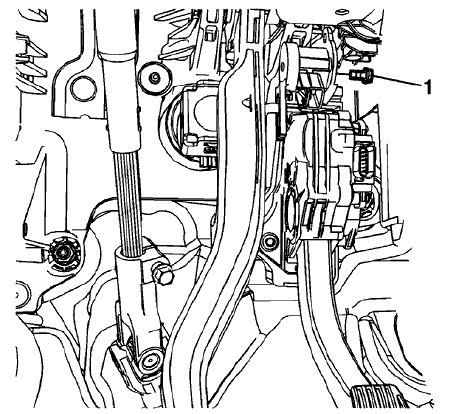
- Remove the brake pedal position sensor bolt (1).
.gif)
Fig. 2: Brake Pedal Position Sensor
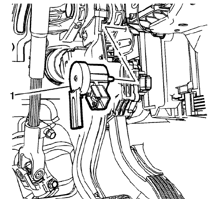
- Remove the brake pedal position sensor (1).
Installation Procedure

Fig. 3: Brake Pedal Position Sensor
NOTE: Ensure the fork of the brake pedal position sensor is positioned over the brake pedal post.Install the brake pedal position sensor (1).
- Install the brake pedal position sensor (1).
.gif)
Fig. 4: Left Side Front Floor Air Outlet Duct
CAUTION: Refer to Fastener Caution
- Install the brake pedal position sensor bolt (1) and tighten to 3 (27 lb in).
- Install the left side front floor air outlet duct. Refer to Floor Front Air Outlet Duct Replacement - Left Side (Encore) , Floor Front Air Outlet Duct Replacement - Left Side (Trax) .
- Connect the brake pedal position sensor electrical connector.
- Calibrate the brake pedal position sensor. Refer to Brake Pedal Position Sensor Calibration

