Chevrolet Trax: Noise and vibration analysis
A noise or vibration that is noticeable when the vehicle is in motion MAY NOT be the result of the transmission.
If noise or vibration is noticeable in PARK and NEUTRAL with the engine at idle, but is less noticeable as RPM increases, the vibration may be a result of poor engine performance.
- Vibration may also be caused by a small amount of water inside the converter.
- Inspect the engine and transmission mounts for damage and loose bolts.
- Inspect the transmission case mounting holes for the following conditions:
- Missing bolts, nuts, and studs
- Stripped threads
- Cracks
- Inspect the flywheel for the following conditions:
- Missing or loose bolts
- Cracks
- Imbalance
- Inspect the torque converter for the following conditions:
- Missing or loose bolts or lugs
- Missing or loose balance weights
- Imbalance caused by heat distortion or fluid contamination
- If the noise or vibration is noticeable in PARK and NEUTRAL with the
engine at idle, but is more
noticeable as RPM increases, the vibration may be an engine imbalance or a
transmission imbalance.
Refer to Torque Converter Diagnosis.
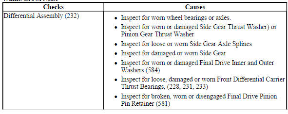
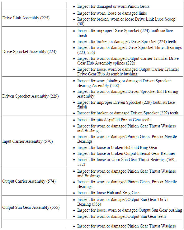
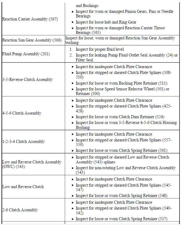
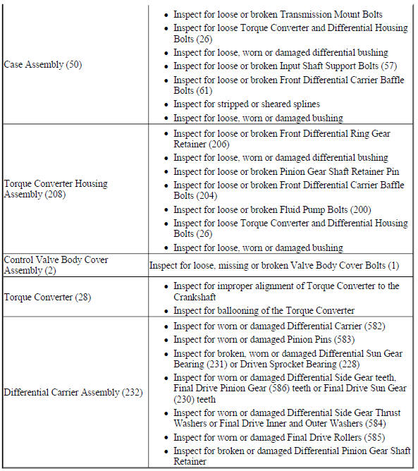
WHINE/GROWL NOISE
Whine/Growl Noise
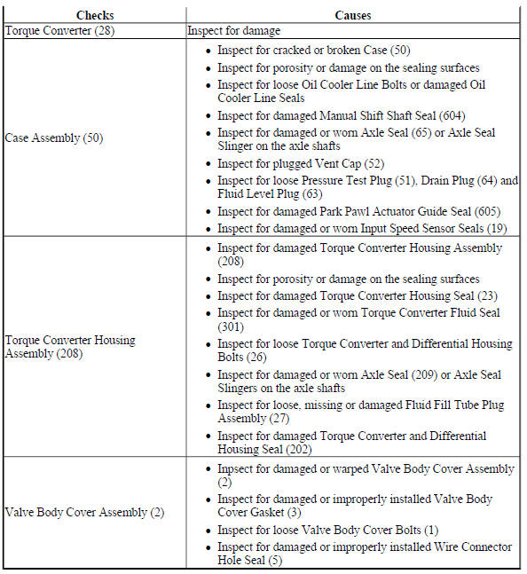
AUTOMATIC TRANSMISSION FLUID LEAKS
Automatic Transmission Fluid Leaks
SHIFT INDICATOR INDICATES WRONG GEAR SELECTION
Shift Indicator Indicates Wrong Gear Selection
.jpg)
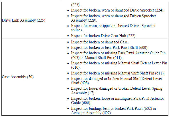
NO PARK
No Park
.jpg)
HARSH GARAGE SHIFT
Harsh Garage Shift
.jpg)
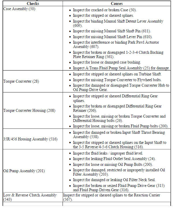
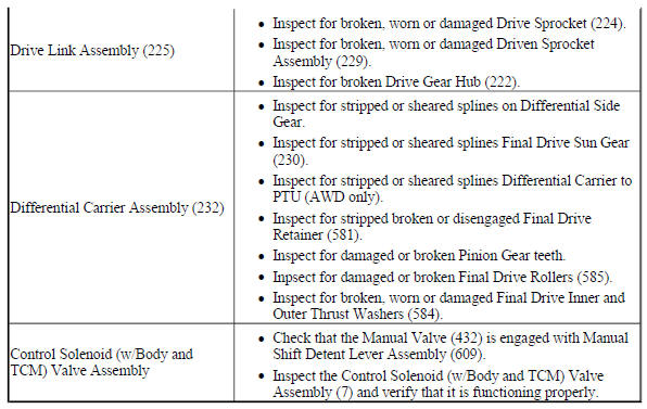
NO DRIVE IN ALL RANGES
No Drive in All Ranges
.jpg)
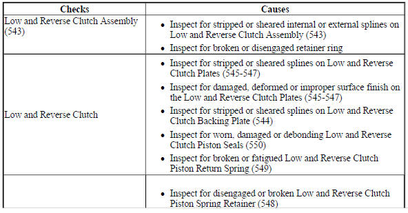
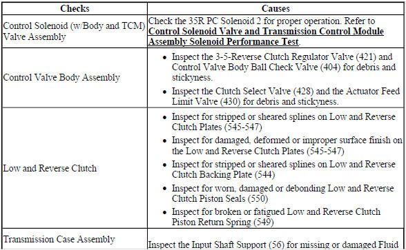
NO FIRST AND REVERSE GEARS
No First and Reverse Gears
.jpg)
NO FIRST, SECOND, THIRD, AND FOURTH GEAR
No First, Second, Third, and Fourth Gear
.jpg)
.jpg)
NO SECOND AND SIXTH GEAR
No Second and Sixth Gear
.jpg)
HARSH OR LATE FIRST, SECOND, THIRD, AND FOURTH SHIFT
Harsh or Late First, Second, Third, and Fourth Shift
.jpg)
.jpg)
HARSH FIRST AND REVERSE SHIFT
Harsh First and Reverse Shift
.jpg)
NO THIRD, FIFTH, AND REVERSE GEAR
No Third, Fifth, and Reverse Gea
.jpg)
.jpg)
HARSH OR LATE SECOND AND SIXTH SHIFT
Harsh or Late Second and Sixth Shift
.jpg)
NO FOURTH, FIFTH, AND SIXTH GEAR
No Fourth, Fifth, and Sixth Gear
.jpg)
HARSH OR LATE THIRD, FIFTH, AND REVERSE SHIFT
Harsh or Late Third, Fifth, and Reverse Shift
.jpg)

HARSH FOURTH, FIFTH, AND SIXTH SHIFT
Harsh Fourth, Fifth, and Sixth Shift
.jpg)
NO TORQUE CONVERTER CLUTCH APPLY
No Torque Converter Clutch Apply
.jpg)
NO TORQUE CONVERTER CLUTCH RELEASE
No Torque Converter Clutch Release
.jpg)
HARSH TORQUE CONVERTER CLUTCH APPLY, OR INOPERATIVE OR NO ELECTRONICALLY CONTROLLED CAPACITY CLUTCH CONTROL
Harsh Torque Converter Clutch Apply, or Inoperative or No Electronically Controlled Capacity Clutch Control
.jpg)
NO REVERSE GEAR
No Reverse Gear
.jpg)
FLUID PRESSURE HIGH OR LOW
Fluid Pressure High or Low
.jpg)
.jpg)
READ NEXT:
 Repair instructions - off vehicle
Repair instructions - off vehicle
Fig. 1: Identifying Lift Plate & Holding Fixture
Lift Plate and Holding Fixture Installation
TORQUE CONVERTER REMOVAL
Fig. 2: View Of Torque Converter
Tor
Input and output speed sensor removal
Fig. 6: View Of Input & Output Speed Sensor
Input and Output Speed Sensor Removal
TORQUE CONVERTER HOUSING WITH FLUID PUMP ASSEMBLY REMOVAL (NON HYBRID)
Fig. 7: View Of Torque Converter Hous
Front wheel drive shaft seal replacement - case side
Fig. 17: View Of Case Side Front Wheel Drive Shaft Seal
Front Wheel Drive Shaft Seal Replacement - Case Side
TRANSMISSION CASE CLEANING AND INSPECTION
Fig. 18: Cleaning & Inspecting Transmis
SEE MORE:
Drum brake adjusting hardware replacement
Removal Procedure
WARNING: Refer to Brake Dust Warning .
Raise and support the vehicle. Refer to Lifting and Jacking the Vehicle
.
Remove the tire and wheel assembly. Refer to Tire and Wheel Removal and
Installation .
Remove the brake drum. Refer to Brake Drum Replacement.
Fig. 40: Upper
DTC B2745 (WITH C67/CJ2): Traction control switch
DIAGNOSTIC CODE INDEX
DTC B2745 (WITH C67/CJ2): Traction control switch
Diagnostic Instructions
Perform the Diagnostic System Check - Vehicle prior to using this
diagnostic procedure.
Review Strategy Based Diagnosis for an overview of the diagnostic
approach.
Diagnostic Procedure Instr
