Chevrolet Trax: DTC B2745 (WITH C67/CJ2): Traction control switch
DIAGNOSTIC CODE INDEX
DTC B2745 (WITH C67/CJ2): Traction control switch
Diagnostic Instructions
- Perform the Diagnostic System Check - Vehicle prior to using this diagnostic procedure.
- Review Strategy Based Diagnosis for an overview of the diagnostic approach.
- Diagnostic Procedure Instructions provides an overview of each diagnostic category.
DTC Descriptors
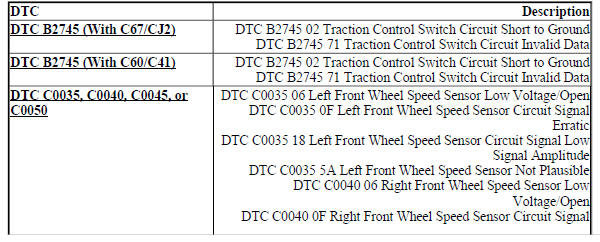
DTC B2745 02
Traction Control Switch Circuit Short to Ground
DTC B2745 71
Traction Control Switch Circuit Invalid Data
Diagnostic Fault Information

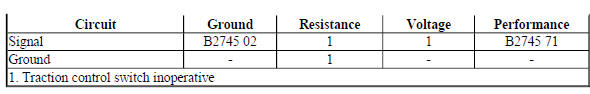
Circuit/System Description
The instrument cluster illuminates the traction/stability control indicator, the traction control off and the stability control off indicator for five seconds after the ignition is turned ON. When the electronic brake control module detects a fault it sends a serial data message to the instrument cluster commanding the traction/stability control indicator ON.
The body control module monitors the signal circuit from the traction control switch. When the traction control switch is pressed once, the body control module sends a serial data message to the electronic brake control module to disable the traction control system. The electronic brake control module will request the instrument cluster to turn the traction control off indicator ON to notify the driver of the deactivation. When the traction control switch is pressed and held for five seconds, the body control module will request the electronic brake control module to disable the electronic stability control. The electronic brake control module will request the instrument cluster to turn the stability control off indicator ON to notify the driver of the deactivation.
Conditions for Running the DTC
- Ignition ON.
- Ignition voltage is greater than 8 V.
Conditions for Setting the DTC
B2745 02
The body control module detects a short to ground on the signal circuit.
B2745 71
The body control module detects an erratic signal from the traction control switch.
Action Taken When the DTC Sets
- The electronic brake control module stores DTC.
- The electronic brake control module disables the vehicle stability for the duration of the ignition cycle.
Conditions for Clearing the DTC
- The conditions for setting the DTC are no longer present.
- The electronic brake control module clears the history DTC when a current DTC is not detected in 40 consecutive drive cycles.
Reference Information
Schematic Reference
Antilock Brake System Schematics (Encore), Antilock Brake System Schematics (Trax)
Connector End View Reference
WIRING SYSTEMS AND POWER MANAGEMENT - COMPONENT CONNECTOR END VIEWS - INDEX - ENCORE WIRING SYSTEMS AND POWER MANAGEMENT - COMPONENT CONNECTOR END VIEWS - INDEX - (Trax)
Description and Operation
ABS Description and Operation
Electrical Information Reference
- Circuit Testing
- Connector Repairs
- Testing for Intermittent Conditions and Poor Connections
- Wiring Repairs
Scan Tool Reference
Control Module References for scan tool information
Circuit/System Verification
- Ignition ON.
- Verify the instrument cluster Traction Control indicator turns On and Off when commanding the instrument cluster All Indicators On and Off with a scan tool.
If the indicator does not turn On and Off
Replace the P16 Instrument Cluster.
If the indicator turns On and Off
- Verify the scan tool Traction Control Switch parameter changes between Active and Inactive while pressing and releasing the traction control switch.
If the parameter does not change
Refer to Circuit/System Testing.
If the parameter changes
- All OK.
Circuit/System Testing
- Ignition OFF, scan tool disconnected, and all vehicle systems OFF, disconnect the harness connector at the S48E Multifunction Switch - Center Console. It may take up to 2 minutes for all vehicle systems to power down.
- Test for less than 10 ohms between the ground circuit terminal 7 and ground.
If 10 ohms or greater
- Ignition OFF.
- Test for less than 2 ohms in the ground circuit end to end.
- If 2 ohms or greater, repair the open/high resistance in the circuit.
- If less than 2 ohms, repair the open/high resistance in the ground connection.
If less than 10 ohms
- Ignition ON.
- Verify the scan tool Body Control Module Traction Control Switch parameter is Inactive.
If not Inactive
- Ignition OFF, disconnect the X2 harness connector at the K9 Body Control Module.
- Test for infinite resistance between the signal circuit terminal 14 and ground.
- If less than infinite resistance, repair the short to ground on the circuit.
- If infinite resistance, replace the K9 Body Control Module.
If Inactive
- Install a 3 A fused jumper wire between the signal circuit terminal 9 and the ground circuit terminal 7.
- Verify the scan tool Traction Control Switch parameter is Active.
If not Active
- Ignition OFF, disconnect the X2 harness connector at the K9 Body Control Module, ignition ON.
- Test for less than 1 V between the signal circuit and ground.
- If 1 V or greater, repair the short to voltage on the circuit.
- If less than 1 V
- Test for less than 2 ohms in the signal circuit end to end.
- If 2 ohms or greater, repair the open/high resistance in the circuit.
- If less than 2 ohms, replace the K9 Body Control Module.
If Active
- Test or replace the S48E Multifunction Switch - Center Console.
Component Testing
- Ignition OFF, disconnect the harness connector at the S48E Multifunction Switch - Center Console.
- Test for infinite resistance between the signal terminal 9 and the ground terminal 7 with the switch in the open position.
If less than infinite resistance
Replace the S48E Multifunction Switch - Center Console.
If infinite resistance
- Test for less than 2 ohms between the signal terminal 9 and the ground terminal 7 with the switch in the closed position.
If 2 ohms or greater
Replace the S48E Multifunction Switch - Center Console.
If less than 2 ohms
- All OK.
Repair Instructions
Perform the Diagnostic Repair Verification after completing the repair.
- Vehicle Stability Control System Switch Replacement
- Control Module References for Body Control Module, Electronic Brake Control Module or Instrument Cluster replacement, programming and setup
READ NEXT:
 DTC B2745 (WITH C60/C41): Traction control switch
Diagnostic Instructions
Perform the Diagnostic System Check - Vehicle prior to using this
diagnostic procedure.
Review Strategy Based Diagnosis for an overview of the diagnostic
approach.
Diag
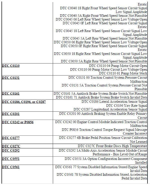
DTC C0035, C0040, C0045, OR C0050: Wheel speed sensor
Diagnostic Instructions
Perform the Diagnostic System Check - Vehicle prior to using this
diagnostic procedure.
Review Strategy Based Diagnosis for an overview of the diagnostic
approach.
Diag
DTC C0110: Pump motor
Diagnostic Instructions
Perform the Diagnostic System Check - Vehicle prior to using this
diagnostic procedure.
Review Strategy Based Diagnosis for an overview of the diagnostic
approach.
Diag
SEE MORE:
Symptoms - vehicle
Body Repair
Symptoms - Bolted Exterior Body Panels and Closures
Body Systems
Symptoms - Fixed and Moveable Windows
Symptoms - Horns
Symptoms - Lighting
Symptoms - Mirrors
Symptoms - Vehicle Access
Symptoms - Wiper/Washer Systems
Brakes
Symptoms - Antilock Brake System
Symptoms - Hydraulic
Interior Lighting
Front and Rear Dome Lamps
The front dome lamp controls are in
the overhead console
: Press to turn the lamps off,
even when a door is open.
: When the button is returned to
the middle position, the lamps turn
on automatically when a door is
opened.
: Press to turn on the dome
lamps.
The rear
