Chevrolet Trax: DTC C0035, C0040, C0045, OR C0050: Wheel speed sensor
Diagnostic Instructions
- Perform the Diagnostic System Check - Vehicle prior to using this diagnostic procedure.
- Review Strategy Based Diagnosis for an overview of the diagnostic approach.
- Diagnostic Procedure Instructions provides an overview of each diagnostic category.
DTC Descriptors
DTC C0035 06
Left Front Wheel Speed Sensor Low Voltage/Open
DTC C0035 0F
Left Front Wheel Speed Sensor Circuit Signal Erratic
DTC C0035 18
Left Front Wheel Speed Sensor Circuit Signal Low Signal Amplitude
DTC C0035 5A
Left Front Wheel Speed Sensor Not Plausible
DTC C0040 06
Right Front Wheel Speed Sensor Low Voltage/Open
DTC C0040 0F
Right Front Wheel Speed Sensor Circuit Signal Erratic
DTC C0040 18
Right Front Wheel Speed Sensor Circuit Signal Low Signal Amplitude
DTC C0040 5A
Right Front Wheel Speed Sensor Not Plausible
DTC C0045 06
Left Rear Wheel Speed Sensor Low Voltage/Open
DTC C0045 0F
Left Rear Wheel Speed Sensor Circuit Signal Erratic
DTC C0045 18
Left Rear Wheel Speed Sensor Circuit Signal Low Signal Amplitude
DTC C0045 5A
Left Rear Wheel Speed Sensor Not Plausible
DTC C0050 06
Right Rear Wheel Speed Sensor Low Voltage/Open
DTC C0050 0F
Right Rear Wheel Speed Sensor Circuit Signal Erratic
DTC C0050 18
Right Rear Wheel Speed Sensor Circuit Signal Low Signal Amplitude
DTC C0050 5A
Right Rear Wheel Speed Sensor Not Plausible
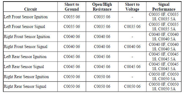
Diagnostic Fault Information
Circuit/System Description
The wheel speeds are detected by active wheel speed sensors and encoder rings. The encoder ring consists of permanent magnets. Each wheel speed sensor receives ignition voltage from the electronic brake control module and provides an alternating current square wave signal to the electronic brake control module. As the wheel spins, the electronic brake control module uses the frequency of the square wave signal to calculate the wheel speed.
Conditions for Running the DTC
C0035 06, C0040 06, C0045 06, or C0050 06
- Ignition ON.
- Ignition voltage is greater than 8 V.
C0035 0F, C0040 0F, C0045 0F, or C0050 0F
- Ignition ON.
- Ignition voltage is greater than 8 V.
- Vehicle speed is greater than 20 km/h (12 MPH).
C0035 18, C0040 18, C0045 18, or C0050 18
- Ignition ON.
- Ignition voltage is greater than 8 V.
- No other wheel speed circuit DTCs are set.
- At least two other wheel speed circuits are not 0 km/h (0 MPH).
C0035 5A, C0040 5A, C0045 5A, or C0050 5A
- Ignition ON.
- Ignition voltage is greater than 8 V.
- The vehicle speed is greater than 20 km/h (12 MPH).
Conditions for Setting the DTC
C0035 06, C0040 06, C0045 06, or C0050 06
- A short to voltage is detected on a wheel speed signal.
- A short to ground or an open/high resistance is detected on a wheel speed signal.
- A short to ground or an open/high resistance is detected on a wheel speed ignition circuit.
C0035 18, C0040 18, C0045 18, or C0050 18
- One wheel speed is less than 2 km/h (1.2 MPH).
- The remaining wheel speeds are greater than 10 km/h (6.2 MPH) for 0.154 seconds.
- The difference between the remaining wheel speeds are less than 4 km/h (2.5 MPH) from each other for more than 2 minutes.
C0035 0F, C0040 0F, C0045 0F, or C0050 0F
The electronic brake control module detected a rapid variation in the wheel speed. The wheel speed changes 20 km/h (12 MPH) or more in 0.7 seconds. The change must occur 56 times with no more than 0.7 seconds between occurrences.
C0035 5A, C0040 5A, C0045 5A, or C0050 5A
The difference between fastest and slowest wheel speed is greater than 60% for more than 2 minutes.
Action Taken When the DTC Sets
- The ABS indicator turns ON.
- The traction/stability control indicator turns ON, if equipped with electronic stability control.
- The electronic brake distribution does not function optimally with multiple wheel speed sensor DTCs set.
- The electronic brake control module disables the ABS, the traction control and the stability control for the duration of the ignition cycle.
Conditions for Clearing the DTC
- The condition for setting the DTC is no longer present.
- The history DTC will clear after 40 consecutive fault-free ignition cycles have occurred.
Diagnostic Aids
- Do not use a magnet to clean the encoder ring.
- Inspect the wheel hub bearing encoder ring for rust or corrosion.
- Inspect the wheel speed sensor for contamination, physical damage, and correct installation.
- If two or more wheel speed sensors are inoperative, diagnose each wheel speed sensor individually.
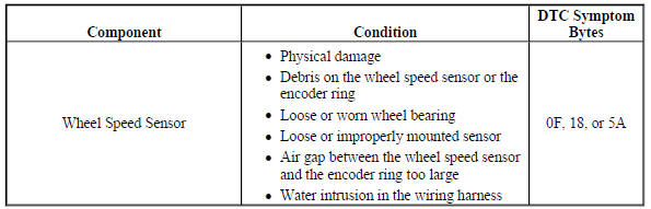
- If any of the symptom codes 0F, 18 or 5A are set, refer to the Diagnostic Fault Information table for possible mechanical faults or conditions.
- If the customer comments that the ABS indicator is ON only during moist environmental conditions (rain, snow, vehicle wash, etc.), inspect the wheel speed sensor wiring for signs of water intrusion.
Reference Information
Schematic Reference
Antilock Brake System Schematics (Encore), Antilock Brake System Schematics (Trax)
Connector End View Reference
WIRING SYSTEMS AND POWER MANAGEMENT - COMPONENT CONNECTOR END VIEWS - INDEX - ENCORE WIRING SYSTEMS AND POWER MANAGEMENT - COMPONENT CONNECTOR END VIEWS - INDEX - (Trax)
Description and Operation
ABS Description and Operation
Electrical Information Reference
- Circuit Testing
- Connector Repairs
- Testing for Intermittent Conditions and Poor Connections
- Wiring Repairs
Scan Tool Reference
Control Module References for scan tool information
Circuit/System Verification
- Test drive the vehicle in a straight line at a speed greater than 40 km/h (25 MPH).
- Verify all scan tool Wheel Speed Sensor parameters are within 4 km/h (2.5 MPH) of each other.
If any parameter is not within 4 km/h (2.5 MPH) of each other
Refer to Circuit/System Testing.
If each parameter is within 4 km/h (2.5 MPH) of each other
- All OK.
Circuit/System Testing
- Ignition OFF and all vehicle systems OFF, disconnect the harness connectors at the appropriate B5 Wheel Speed Sensor and the harness connector at the K17 Electronic Brake Control Module, ignition ON.
- Test for less than 1 V between the appropriate K17 Electronic Brake Control Module harness connector terminals listed below and ground:
- B5LF Wheel Speed Sensor - Left Front - terminal 34 and terminal 21
- B5LR Wheel Speed Sensor - Left Rear - terminal 33 and terminal 20
- B5RF Wheel Speed Sensor - Right Front - terminal 18 and terminal 31
- B5RR Wheel Speed Sensor - Right Rear - terminal 19 and terminal 32
If 1 V or greater
Repair the short to voltage on the circuit.
If less than 1 V
- Ignition OFF.
- Test for infinite resistance between the K17 Electronic Brake Control Module harness connector terminals listed below and ground:
- B5LF Wheel Speed Sensor - Left Front - terminal 34 and terminal 21
- B5LR Wheel Speed Sensor - Left Rear - terminal 33 and terminal 20
- B5RF Wheel Speed Sensor - Right Front - terminal 18 and terminal 31
- B5RR Wheel Speed Sensor - Right Rear - terminal 19 and terminal 32
If less than infinite resistance
Repair the short to ground on the circuit.
If infinite resistance
- Test for less than 2 ohms between the B5 Wheel Speed Sensor harness connector terminal 1 and the K17 Electronic Brake Control Module harness connector terminal listed below:
- B5LF Wheel Speed Sensor - Left Front - terminal 34
- B5LR Wheel Speed Sensor - Left Rear - terminal 33
- B5RF Wheel Speed Sensor - Right Front - terminal 18
- B5RR Wheel Speed Sensor - Right Rear - terminal 19
If 2 ohms or greater
Repair the open/high resistance in the circuit.
If less than 2 ohms
- Test for less than 2 ohms between the B5 Wheel Speed Sensor harness connector terminal 2 and the K17 Electronic Brake Control Module harness connector terminal listed below:
- B5LF Wheel Speed Sensor - Left Front - terminal 21
- B5LR Wheel Speed Sensor - Left Rear - terminal 20
- B5RF Wheel Speed Sensor - Right Front - terminal 31
- B5RR Wheel Speed Sensor - Right Rear - terminal 32
If 2 ohms or greater
Repair the open/high resistance in the circuit.
If less than 2 ohms
- Replace the B5 Wheel Speed Sensor.
- Verify the DTC does not set while operating the vehicle within the Conditions for Running the DTC.
If the DTC sets
Replace the K17 Electronic Brake Control Module.
If the DTC does not set
- All OK.
Repair Instructions
Perform the Diagnostic Repair Verification after completing the repair.
- Front Wheel Speed Sensor Replacement
- Rear Wheel Speed Sensor Replacement
- Control Module References for Electronic Brake Control Module replacement, programming and setup
READ NEXT:
 DTC C0110: Pump motor
Diagnostic Instructions
Perform the Diagnostic System Check - Vehicle prior to using this
diagnostic procedure.
Review Strategy Based Diagnosis for an overview of the diagnostic
approach.
Diag
DTC C0131: Traction control system pressure circuit
Diagnostic Instructions
Perform the Diagnostic System Check - Vehicle prior to using this
diagnostic procedure.
Review Strategy Based Diagnosis for an overview of the diagnostic
approach.
Diag
DTC C0161: Antilock brake system brake switch
Diagnostic Instructions
Perform the Diagnostic System Check - Vehicle prior to using this
diagnostic procedure.
Review Strategy Based Diagnosis for an overview of the diagnostic
approach.
Diag
SEE MORE:
Remote functions - Description and operation
KEYLESS ENTRY SYSTEM DESCRIPTION AND OPERATION
The keyless entry system is a vehicle entry device. The keyless entry system
is used in conjunction with the
door locks to unlock the vehicle. Keyless entry will lock/unlock the vehicle
doors or open the rear compartment
lid when a corresponding butto
Drive Range, Fourth Gear Default - Gen 2/Hybrid
Fig. 14: Drive Range, Fourth Gear Default -- Gen 2/Hybrid Fluid Flow Diagram
Drive Range, Fifth Gear (Gen 2/Hybrid)
As vehicle speed increases, the transmission control module (TCM) processes
input signals from the automatic
transmission input and output speed sensors, the throttle position senso
