Chevrolet Trax: DTC C0110: Pump motor
Diagnostic Instructions
- Perform the Diagnostic System Check - Vehicle prior to using this diagnostic procedure.
- Review Strategy Based Diagnosis for an overview of the diagnostic approach.
- Diagnostic Procedure Instructions provides an overview of each diagnostic category.
DTC Descriptors
DTC C0110 04
Pump Motor Circuit Open
DTC C0110 06
Pump Motor Circuit Low Voltage/Open
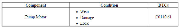
DTC C0110 61
Pump Motor Stuck
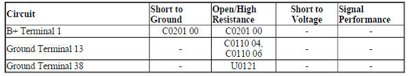
Diagnostic Fault Information
Circuit/System Description
The pump motor is an integral part of the brake pressure modulator, while the pump motor relay is integral to the electronic brake control module. The pump motor relay is not engaged during normal system operation.
When ABS operation is required the electronic brake control module activates the pump motor relay and battery voltage is provided to the pump motor.
Conditions for Running the DTC
C0110 04 or C0110 06
Ignition ON.
C0110 61
- The vehicle speed is greater than 20 km/h (13 MPH), and brake is not applied.
- The test is initiated once per ignition cycle, when the vehicle speed is greater than 15 km/h (9 MPH), and a fault was set on the last ignition cycle.
Conditions for Setting the DTC
C0110 04 or C0110 06
- The ground circuit is open, and the feedback voltage is greater than 5 V for 0.5 seconds, the pump is not activated.
- The electronic brake control module detects a low voltage in the pump motor supply circuit when the feedback voltage is less than 5 V for greater than 500 ms, and the pump motor is not activated.
C0110 61
The pump motor continues to rotate briefly after deactivation creating a feedback voltage. The electronic brake control module sets the DTC if the measured feedback voltage indicates a binding or stalled pump motor.
Action Taken When the DTC Sets
- The ABS indicator turns ON.
- The traction/stability control indicator turns ON, if equipped with electronic stability control.
- The electronic brake control module disables the ABS, the traction control and the electronic stability control for the duration of the ignition cycle.
Conditions for Clearing the DTC
- The condition for setting the DTC is no longer present.
- The history DTC will clear after 40 consecutive fault-free ignition cycles have occurred.
Reference Information
Schematic Reference
Antilock Brake System Schematics (Encore), Antilock Brake System Schematics (Trax)
Connector End View Reference
WIRING SYSTEMS AND POWER MANAGEMENT - COMPONENT CONNECTOR END VIEWS - INDEX - ENCORE WIRING SYSTEMS AND POWER MANAGEMENT - COMPONENT CONNECTOR END VIEWS - INDEX - (Trax)
Description and Operation
ABS Description and Operation
Electrical Information Reference
- Circuit Testing
- Connector Repairs
- Testing for Intermittent Conditions and Poor Connections
- Wiring Repairs
Scan Tool Reference
Control Module References for scan tool information
Circuit/System Verification
- Ignition ON
- Verify the ABS pump motor turns ON and OFF when commanding the ABS Pump Motor ON and OFF with a scan tool
If the pump motor does not turn ON and OFF
Refer to Circuit/System Testing
If the pump motor turns ON and OFF
- All OK.
Circuit/System Testing
- Ignition OFF and all vehicle systems OFF, disconnect the harness connector at the K17 Electronic Brake Control Module. It may take up to 2 min for all vehicle systems to power down.
- Test for less than 10 ohms between the ground circuit terminals listed below and ground:
- Terminal 13
- Terminal 38
If 10 ohms or greater
- Ignition OFF
- Test for less than 2 ohms in the ground circuit end to end.
- If 2 ohms or greater, repair the open/high resistance in the circuit.
- If less than 2 ohms, repair the open/high resistance in the ground connection.
If less than 10 ohms
- Ignition ON.
- Verify a test lamp illuminates between the B+ circuit terminal 1 and ground.
If the test lamp does not illuminate and the circuit fuse is good
- Ignition OFF.
- Test for less than 2 ohms in the B+ circuit end to end.
- If 2 ohms or greater, repair the open/high resistance in the circuit.
- If less than 2 ohms, verify the fuse is not open and there is voltage at the fuse.
If the test lamp does not illuminate and the circuit fuse is open
- Ignition OFF.
- Test for infinite resistance between the B+ circuit and ground.
- If less than infinite resistance, repair the short to ground on the circuit.
- If infinite resistance, replace the Q5 Brake Pressure Modulator.
If the test lamp illuminates
- Replace the Q5 Brake Pressure Modulator.
- Verify the DTC does not set while operating the vehicle within the Conditions for Running the DTC.
If the DTC sets
Replace the K17 Electronic Brake Control Module.
If the DTC does not set
- All OK.
Repair Instructions
Perform the Diagnostic Repair Verification after completing the repair.
- Brake Pressure Modulator Valve Replacement
- Control Module References for Electronic Brake Control Module replacement, programming and setup
READ NEXT:
 DTC C0131: Traction control system pressure circuit
Diagnostic Instructions
Perform the Diagnostic System Check - Vehicle prior to using this
diagnostic procedure.
Review Strategy Based Diagnosis for an overview of the diagnostic
approach.
Diag
DTC C0161: Antilock brake system brake switch
Diagnostic Instructions
Perform the Diagnostic System Check - Vehicle prior to using this
diagnostic procedure.
Review Strategy Based Diagnosis for an overview of the diagnostic
approach.
Diag
DTC C0186, C0196, OR C0287: Lateral acceleration sensor/yaw rate sensor/lateral
acceleration sensor
Diagnostic Instructions
Perform the Diagnostic System Check - Vehicle prior to using this
diagnostic procedure.
Review Strategy Based Diagnosis for an overview of the diagnostic
approach.
Diag
SEE MORE:
DTC B3715 OR B3875: Windshield wiper relay
Diagnostic Instructions
Perform the Diagnostic System Check - Vehicle prior to using this
diagnostic procedure.
Review Strategy Based Diagnosis for an overview of the diagnostic
approach.
Diagnostic Procedure Instructions provides an overview of each
diagnostic category
DTC Descriptors
DT
HVAC System malfunction (C67)
Diagnostic Instructions
Perform the Diagnostic System Check - Vehicle prior to using this
diagnostic procedure.
Review Strategy Based Diagnosis for an overview of the diagnostic
approach.
Diagnostic Procedure Instructions provides an overview of each
diagnostic category.
Diagnostic Aids
C
