Chevrolet Trax: DTC B3715 OR B3875: Windshield wiper relay
Diagnostic Instructions
- Perform the Diagnostic System Check - Vehicle prior to using this diagnostic procedure.
- Review Strategy Based Diagnosis for an overview of the diagnostic approach.
- Diagnostic Procedure Instructions provides an overview of each diagnostic category
DTC Descriptors
DTC B3715
Windshield Wiper Relay Circuit
DTC B3875
Windshield Wiper High Speed Relay Circuit
For symptom byte information, refer to Symptom Byte List .
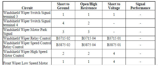
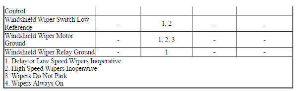
Diagnostic Fault Information
Circuit/System Description
The body control module (BCM) controls the windshield wiper motor based on inputs from the windshield wiper/washer switch. The BCM monitors the windshield wiper/washer switch through two separate signal circuits and a low reference circuit. The windshield wiper/washer switch uses a resistor ladder to determine low speed and intermittent operation. The BCM monitors applies and monitors voltage on the windshield wiper switch signal circuit. When the wiper switch is placed in the low speed or intermittent position, the voltage is pulled down through a different resistor in the resistor ladder, reducing the voltage seen at the BCM. The BCM will respond by commanding on the low speed or intermittent wipers. The high speed wipers are controls through a discrete signal circuit. With the windshield wiper/washer switch is in the high speed position, the windshield wiper high speed switch signal circuit is pulled directly to ground. The BCM will respond by commanding on the high speed wipers.
The windshield wiper motor is controlled by the BCM through the windshield wiper replay and the windshield wiper speed control relay. A constant and ground is supplied to the rear wiper motor. When low speed windshield wiper operation is requested, the BCM will apply voltage to the windshield wiper relay control circuit. This will cause the contacts in the windshield wiper relay to close and apply B+ to the windshield wiper motor through the windshield wiper low speed control circuit, enabling low speed wiper operation. When high speed windshield wiper operation is requested, the BCM continues to apply voltage to the windshield wiper relay control circuit and also applies ground to the windshield wiper speed control relay control circuit. This will cause the contacts in the windshield wiper speed control relay to close and apply B+ to the windshield wiper motor through the windshield wiper high speed control circuit, enabling high speed wiper operation.
When the windsheild wiper request is no longer present, the contacts in the windshield wiper relay and windshield wiper speed control relay will open, removing B+ from the wiper motor control circuits. The windshield wiper motor will continue to operate using a discrete B+ circuit provided by the BCM until the wipers are in the park position.
Conditions for Running the DTC
- A wiper output is actively being requested by the BCM.
- The system voltage is between 9-16 V.
Conditions for Setting the DTC
B3715 01
A short to voltage is detected in the windshield wiper relay control circuit.
B3715 02
A short to ground is detected in the windshield wiper relay control circuit.
B3715 04
An open or high resistance is detected in the windshield wiper relay control circuit.
B3875 01
A short to voltage is detected in the windshield wiper high speed relay control circuit.
B3875 02
A short to ground is detected in the windshield wiper high speed relay control circuit.
B3875 04
An open or high resistance is detected in the windshield wiper high speed relay control circuit.
Action Taken When the DTC Sets
The BCM will not activate the wiper output.
Conditions for Clearing the DTC
- A current DTC will clear when the condition for setting the fault is no longer present.
- A history DTC will clear after 50 consecutive ignition cycles without a fault present.
Reference Information
Schematic Reference
Wiper/Washer Schematics (Encore), Wiper/Washer Schematics (Trax)
Connector End View Reference
WIRING SYSTEMS AND POWER MANAGEMENT - COMPONENT CONNECTOR END VIEWS - INDEX - ENCORE WIRING SYSTEMS AND POWER MANAGEMENT - COMPONENT CONNECTOR END VIEWS - INDEX - TRAX
Description and Operation
Wiper/Washer System Description and Operation
Electrical Information Reference
- Circuit Testing
- Connector Repairs
- Testing for Intermittent Conditions and Poor Connections
- Wiring Repairs
Scan Tool Reference
Control Module References for scan tool information
Circuit/System Verification
- Ignition ON.
- Verify the scan tool Windshield Wiper Switch parameter changes between Off and Low when activating the low speed windshield wipers.
If the parameter does not change
Refer to Circuit/System Testing - Windshield Wiper/Washer Switch Malfunction.
If the parameter changes
- Verify the scan tool Windshield Wiper Switch parameter changes between Delay 1 and Delay 5 when cycling the intermittent speed windshield wipers.
If the parameter does not change
Test or replace the S82 Windsheild Wiper/Washer Switch.
If the parameter changes
- Verify the scan tool Windshield Wiper High Speed Switch parameter changes between Active and Inactive when activating the high speed windshield wipers.
If the parameter does not change
Refer to Circuit/System Testing - Windshield Wiper/Washer Switch Malfunction.
If the parameter changes
- Verify the M75 Windshield Wiper Motor changes between Off, Low, and High when cycling the S82 Windshield Wiper/Washer Switch between Off, Low, and High.
If the Windshield Wiper Motor does not cycle between Off, Low, and High
Refer to Circuit/System Testing - Windshield Wiper Motor Malfunction
If the Windshield Wiper Motor cycles between Off, Low, and High
- Ignition OFF.
- Verify the scan tool Windshield Wiper Park Switch parameter is Active.
If the parameter does not change
Refer to Circuit/System Testing - Windshield Wiper Motor Malfunction.
If the parameter changes
- All OK.
Circuit/System Testing
Windshield Wiper/Washer Switch Malfunction
- Ignition OFF and all vehicle systems OFF, disconnect the harness connector at the S82 Windshield Wiper/Washer Switch. It may take up to 11 min for all vehicle systems to power down.
- Test for less than 10 ohms between the low reference circuit terminal 2 and ground.
If 10 ohms or greater
- Ignition OFF, disconnect the X3 harness connector at the K9 Body Control Module.
- Test for less than 2 ohms in the low reference circuit end to end.
- If 2 ohms or greater, repair the open/high resistance in the circuit.
- If less than 2 ohms, replace the K9 Body Control Module.
If less than 10 ohms
- Ignition ON.
- Verify the scan tool Windshield Wiper High Speed Switch parameter is Inactive.
If not Inactive
- Ignition OFF, disconnect the X3 harness connector at the K9 Body Control Module.
- Test for infinite resistance between the signal circuit terminal 1 and ground.
- If less than infinite resistance, repair the short to ground on the circuit.
- If infinite resistance, replace the K9 Body Control Module.
If Inactive
- Install a 3 A fused jumper wire between the signal circuit terminal 1 and the low reference circuit terminal 2.
- Verify the scan tool Windshield Wiper High Speed Switch parameter is Active.
If not Active
- Ignition OFF, remove the jumper wire, disconnect the X3 harness connector at the K9 Body Control Module, ignition ON.
- Test for less than 1 V between the signal circuit and ground.
- If 1 V or greater, repair the short to voltage on the circuit.
- If less than 1 V
- Test for less than 2 ohms in the signal circuit end to end.
- If 2 ohms or greater, repair the open/high resistance in the circuit.
- If less than 2 ohms, replace the K9 Body Control Module.
If Active
- Test for greater than 8 V between the signal circuit terminal 3 and ground.
If less than 8 V
- Ignition OFF, disconnect the X3 harness connector at the K9 Body Control Module.
- Test for infinite resistance between the signal circuit and ground
- If less than infinite resistance, repair the short to ground on the circuit.
- If infinite resistance
- Test for less than 2 ohms in the signal circuit end to end.
- If 2 ohms or greater, repair the open/high resistance in the circuit.
- If less than 2 ohms, replace the K9 Body Control Module.
If 8 V or greater
- Ignition OFF, disconnect the X3 harness connector at the K9 Body Control Module, ignition ON.
- Test for less than 1 V between the S82 Windshield Wiper/Washer Switch signal circuit terminal 3 and ground
If 1 V or greater
Repair the short to voltage on the circuit.
If less than 1 V
- Test or replace the S82 Windshield Wiper/Washer Switch.
Windshield Wiper Motor Malfunction
- Ignition OFF and all vehicle systems OFF, disconnect the harness connector at the M75 Windshield Wiper Motor. It may take up to 2 min for all vehicle systems to power down.
- Test for less than 10 ohms between the ground circuit terminal 1 and ground.
If 10 ohms or greater
- Ignition OFF.
- Test for less than 2 ohms in the ground circuit end to end.
- If 2 ohms or greater, repair the open/high resistance in the circuit.
- If less than 2 ohms, repair the open/high resistance in the ground connection.
If less than 10 ohms
- Ignition ON.
- Verify the scan tool Windshield Wiper Park Switch parameter is Inactive.
If not Inactive
- Ignition OFF, disconnect the X4 harness connector at the K9 Body Control Module.
- Test for infinite resistance between the M75 Windshield Wiper Motor signal circuit terminal 2 and ground.
- If less than infinite resistance, repair the short to ground on the circuit.
- If infinite resistance, replace the K9 Body Control Module.
If Inactive
- Install a 3 A fused jumper wire between the signal circuit terminal 2 and ground.
- Verify the scan tool Windshield Wiper Park Switch parameter is Active.
If not Active
- Ignition OFF, remove the jumper wire, disconnect the X4 harness connector at the K9 Body Control Module, ignition ON.
- Test for less than 1 V between the signal circuit and ground.
- If 1 V or greater, repair the short to voltage on the circuit.
- If less than 1 V
- Test for less than 2 ohms in the signal circuit end to end.
- If 2 ohms or greater, repair the open/high resistance in the circuit.
- If less than 2 ohms, replace the K9 Body Control Module.
If Active
- Connect a test lamp between the following control circuits and ground, ignition ON.
- Control Circuit Terminal 4
- Control Circuit Terminal 5
- Verify the test lamp does NOT turn ON and OFF when commanding the appropriate Windshield Wiper Relay On and Off with a scan tool.
If the test lamp turns ON and OFF for both terminals
Test or replace the M75 Windshield Wiper Motor.
If the test lamp does not turn ON and OFF for one or both terminals
- Ignition OFF and all vehicle systems OFF, connect the harness connector at the M75 Windshield Wiper Motor. Disconnect the X2 harness connector at the X50A Fuse Block - Underhood. It may take up to 2 min for all vehicle systems to power down.
- Test for less than 10 ohms between the ground circuit terminals listed below and ground:
- Terminal C5
- Terminal H1
If 10 ohms or greater
- Ignition OFF.
- Test for less than 2 ohms in the ground circuit end to end.
- If 2 ohms or greater, repair the open/high resistance in the circuit.
- If less than 2 ohms, repair the open/high resistance in the ground connection.
If less than 10 ohms
- Ignition ON.
- Verify the M75 Windshield Wiper Motor is not activated.
If the M75 Windshield Wiper Motor is activated
- Ignition OFF, disconnect the harness connector at the M75 Windshield Wiper Motor, ignition ON.
- Test for less than 1 V between each control circuit listed below and ground:
- Terminal 4
- Terminal 5
If 1 V or greater, repair the short to voltage on the circuit.
If less than 1 V, replace the M75 Windshield Wiper Motor.
If the M75 Windshield Wiper Motor is not activated
- Connect a 20 A fused jumper wire between the control circuit terminals listed below, one at a time, and B+.
- Terminal H2
- Terminal C1
- Verify the M75 Windshield Wiper Motor activates.
If the M75 Windshield Wiper Motor does not activate
- Ignition OFF, remove the jumper wire, disconnect the harness connector at the M75 Windshield Wiper Motor.
- Test for infinite resistance between the control circuit and ground.
- If less than Infinite resistance, repair the short to ground on the circuit.
- If infinite resistance
- Test for less than 2 ohms in the control circuit end to end.
- If 2 ohms or greater, repair the open/high resistance in the circuit.
- If less than 2 ohms, replace the M75 Windshield Wiper Motor.
If the M75 Windshield Wiper Motor activates
- Ignition OFF, connect the X2 harness connector at the X50A Fuse Block - Underhood. Disconnect the X4 harness connector at the K9 Body Control Module, ignition ON.
- Verify the M75 Windshield Wiper Motor low speed is not activated.
If the M75 Windshield Wiper Motor low speed is activated
- Ignition OFF, disconnect the X2 harness connector at the X50A Fuse Block - Underhood, ignition ON.
- Test for less than 1 V between the control circuit terminal D3 and ground.
- If 1 V or greater, repair the short to voltage on the circuit.
- If less than 1 V, replace the X50A Fuse Block - Underhood.
If the M75 Windshield Wiper Motor low speed is not activated
- Ignition OFF, disconnect the X5 harness connector at the K9 Body Control Module, ignition ON.
- Verify the M75 Windshield Wiper Motor High Speed is not activated.
If the M75 Windshield Wiper Motor high speed is activated
- Ignition OFF, disconnect the X2 harness connector at the X50A Fuse Block - Underhood, ignition ON.
- Test for infinite resistance between the control circuit terminal D2 and ground.
- If less than infinite resistance, repair the short to ground on the circuit.
- If infinite resistance, replace the X50A Fuse Block - Underhood.
If the M75 Windshield Wiper Motor high speed is not activated
- Connect a 10 A fused jumper wire between the control circuit terminal 16 X4 and B+.
- Verify the M75 Windshield Wiper Motor activates.
If the M75 Windshield Wiper Motor does not activate
- Ignition OFF, remove the jumper wire, disconnect the X2 harness connector at the X50A Fuse Block - Underhood.
- Test for infinite resistance between the control circuit and ground.
- If less than infinite resistance, repair the short to ground on the circuit.
- If less than infinite resistance
- Test for less than 2 ohms in the control circuit end to end.
- If 2 ohms or greater, repair the open/high resistance in the circuit.
- If less than 2 ohms, test or replace the X50A Fuse Block - Underhood.
If the M75 Windshield Wiper Motor activates
- Connect a 10 A fused jumper wire between the control circuit terminal 24 X5 and ground.
- Verify the M75 Windshield Wiper Motor activates.
If the M75 Windshield Wiper Motor does not activate
- Ignition OFF, remove the jumper wire, disconnect the X2 harness connector at the X50A Fuse Block - Underhood.
- Test for less than 1 V between the control circuit and ground.
- If 1 V or greater, repair the short to ground on the circuit.
- If less than 1 V
- Test for less than 2 ohms in the control circuit end to end.
- If 2 ohms or greater, repair the open/high resistance in the circuit.
- If less than 2 ohms, test or replace the X50A Fuse Block - Underhood.
If the M75 Windshield Wiper Motor activates
- Replace the K9 Body Control Module.
Component Testing
Windshield Wiper/Washer Switch
- Ignition OFF, disconnect the harness connector at the S82 Windshield Wiper/Washer Switch.
- Test for infinite resistance between the signal terminal 1 and the low reference terminal 2 with the switch in the open position.
If less than infinite resistance
Replace the S82 Windshield Wiper/Washer Switch.
If infinite resistance
- Test for less than 2 ohms between the signal circuit terminal 1 and the low reference circuit terminal 2 with the switch in the closed position.
If 2 ohms or greater
Replace the S82 Windshield Wiper/Washer Switch.
If less than 2 ohms
- Test for infinite resistance between the signal terminal 3 and the low reference terminal 2 with the switch in the open position.
If less than infinite resistance
Replace the S82 Windshield Wiper/Washer Switch.
If infinite resistance
- Verify the resistance readings are within the specified range listed below between the signal circuit terminal 3 and the low reference circuit terminal 2 by pushing the switch in the listed positions below.
- Delay 1 : 3.75-3.85kohms
- Delay 2 : 2.75-2.85kohms
- Delay 3 : 1.95-2.05kohms
- Delay 4 : 1.25-1.35kohms
- Delay 5 : 765-775ohms
If not within the specified range
Replace the S82 Windshield Wiper/Washer Switch.
If within the specified range
- All OK
Repair Instructions
Perform the Diagnostic Repair Verification after completing the repair.
- Windshield Wiper Motor Replacement
- Front Compartment Fuse Block Replacement
- Windshield Wiper and Washer Switch Replacement (Encore), Windshield Wiper and Washer Switch Replacement (Trax)
- Control Module References for body control module replacement, programming, and setup.
READ NEXT:
 DTC B3811: Rear washer relay
Diagnostic Instructions
Perform the Diagnostic System Check - Vehicle prior to using this
diagnostic procedure.
Review Strategy Based Diagnosis for an overview of the diagnostic
approach.
Diag
DTC B3873: Front washer relay
Diagnostic Instructions
Perform the Diagnostic System Check - Vehicle prior to using this
diagnostic procedure.
Review Strategy Based Diagnosis for an overview of the diagnostic
approach.
Diag
Symptoms - wiper/washer systems
NOTE: The following steps must be completed before using the
symptom tables:
Perform Diagnostic System Check - Vehicle , in order to verify that all
of the following conditions are
true:
No D
SEE MORE:
Symptoms - bolted exterior body panels and closures
IMPORTANT: The following steps must be completed before using the
symptom tables.
Perform the Diagnostic System Check - Vehicle before using the symptom
tables in order to verify that
all of the following are true:
There are no DTCs set.
The control modules can communicate via the serial d
Door Locks
To lock or unlock a door manually:
From the inside, to lock the door,
use the lock knob on the top of
the door panel.
From the outside, turn the key
toward the front or rear of the
vehicle, or press or
on the
Remote Keyless Entry (RKE)
transmitter.
Power Door Locks
: Press to unlock
