Chevrolet Trax: Headlamp aiming
Visual Aiming Preparation Procedure
NOTE: Some state and local laws specify requirements for headlamp aim. Comply with all of these laws when performing any headlamp aiming operations.
Headlamp aim should be checked:
- When a new headlamp capsule is installed.
- If service or repairs to the front end area have, or may have, disturbed the headlamps or their mounting.
The aiming screen should meet the following criteria:
- The area will consist of a level surface large enough to allow for a vehicle and an additional 7.62 m (25 ft) measured from face of lamps to the front of the aiming screen.
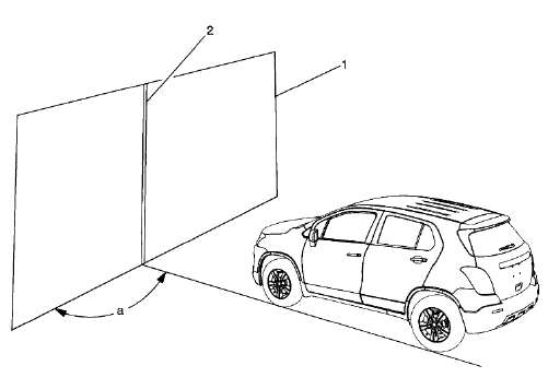
- The screen will be 1.52 m (5 ft) high x 3.66 m (12 ft) wide with a matte white surface well shaded from extraneous light, and properly adjusted to the floor on which the vehicle stands. Provisions should be made to align the aiming screen parallel with the vehicle.
- The screen shall be provided with a fixed vertical centerline, two
laterally adjustable vertical tapes, and
one vertically adjustable horizontal tape.
If a regular commercial aiming screen is not available, the screen may consist of a vertical wall having a clear uninterrupted area approximately 1.83 m (6 ft) high and 3.66 m (12 ft) wide. The surface should be finished with a washable non-gloss white paint.
.gif)
Fig. 29: Headlamp Alignment Screen
After the aiming screen has been set up in a permanent location, paint a reference line on the floor directly under the lens of the lamps to indicate the proper location of the headlamps when they are being aimed:
- Adjustable horizontal tape (1)
- Adjustable vertical pointer (2)
- Diagram of light screen (3)
- Distance between headlamps (4)
- Center line of screen (5)
- Horizontal center line of lamps (6)
- 7.62 m (25 ft) (7)
- Car axis (8)
- Horizontal center line ahead of left headlamp (9)
Prior to aiming the headlamps, the following steps must be taken:
- Remove any snow, ice or mud from the vehicle.
- The vehicle must have a full tank of gas.
- Stop all other work on the vehicle.
- If any service has been performed on the vehicle, make sure that all of the components are back in their original place.
- The vehicle must be on a level surface.
- The vehicle left tires must be aligned with the reference line extending from the screen with the headlamps aligned with the reference line.
- Do not load any cargo in the vehicle.
- The vehicle must contain approximately 75 kg (165 lb) on the driver seat.
- Inflate the tires to the proper pressure.
- Simulate the vehicle loads if the intended use of the vehicle is for hauling heavy loads or towing a trailer.
- Rock the vehicle in order to stabilize the suspension.
- Turn on the headlamps to low beam and observe the left and the top edges of the high intensity zone on the screen. The edges of the high intensity zone should fall within the specifications.
Headlamp Aiming Procedure

Fig. 30: Headlamp Alignment Screen Marks
- Open the hood.
- Measure from the floor to the center of the headlamp bulb. Some headlamps have an aim dot marked on the headlamp lens.
- At the screen, measure from the floor and place the horizontal tape at the measured distance.
- Measure from the reference line on the floor to the left headlamp bulb centerline.
- At the screen (1), measure from the reference line and place the vertical tape at the measured distance.
- Measure from the reference line on the floor to the right headlamp bulb centerline.
- At the screen, measure from the reference line and place the vertical tape (2) at the measured distance.
.gif)
Fig. 31: Identifying Right Side Low Beam Proper Screen Positioning
NOTE: DO NOT cover the headlamp. This may cause excessive heat build up.
- Turn ON the low beam headlamps. Block the light from projecting onto the screen from the passenger side headlamp.
.gif)
Fig. 32: Headlamp Adjustment Screws
- Adjust the vertical aim screw ( as shown by the arrow ) of the headlamps to the specifications required by the state and the local authorities, or as shown in step number 8.
- Repeat the aiming procedure for the passenger side headlamp while blocking the light from projecting onto the screen from the driver side headlamp.
- Turn the headlamps OFF.
- Close the hood.

