Chevrolet Trax: Schematic wiring diagrams
HEADLIGHTS/DAYTIME RUNNING LIGHTS (DRL) WIRING SCHEMATICS (ENCORE)
Controls and Indicators
.jpg)
Fig. 1: Controls and Indicators
HeadLamps
.jpg)
Fig. 2: HeadLamps
Leveling (TR6)
.jpg)
Fig. 3: Leveling (TR6)
HEADLIGHTS/DAYTIME RUNNING LIGHTS (DRL) WIRING SCHEMATICS (TRAX)
Controls and Indicators
.jpg)
Fig. 4: Controls and Indicators
HeadLamps (Without T3N)
.jpg)
Fig. 5: HeadLamps (Without T3N)
HeadLamps (T3N)
.jpg)
Fig. 6: HeadLamps (T3N)
Leveling (TR6)
.jpg)
Fig. 7: Leveling (TR6)
FOG LIGHTS WIRING SCHEMATICS (ENCORE)
Fog Lamps
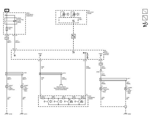
Fig. 8: Fog Lamps
FOG LIGHTS WIRING SCHEMATICS (TRAX)
Fog Lamps
.jpg)
Fig. 9: Fog Lamps
EXTERIOR LIGHTS WIRING SCHEMATICS (ENCORE)
Park, Turn, Hazard and Brake Lamp Controls, and Indicators
.jpg)
Fig. 10: Park, Turn, Hazard and Brake Lamp Controls, and Indicators
Park, Repeater and Front Turn Lamps
.jpg)
Fig. 11: Park, Repeater and Front Turn Lamps
Tail, Stop and Rear Turn Signal Lamps
.jpg)
Fig. 12: Tail, Stop and Rear Turn Signal Lamps
License Plate and Backup Lamps
.jpg)
Fig. 13: License Plate and Backup Lamps
EXTERIOR LIGHTS WIRING SCHEMATICS (TRAX)
Park, Turn, Hazard and Brake Lamp Controls, and Indicators
.jpg)
Fig. 14: Park, Turn, Hazard and Brake Lamp Controls, and Indicators
Park, Repeater and Front Turn Lamps
.jpg)
Fig. 15: Park, Repeater and Front Turn Lamps
Tail, Stop and Rear Turn Signal Lamps
.jpg)
Fig. 16: Tail, Stop and Rear Turn Signal Lamps
License Plate and Backup Lamps
.jpg)
Fig. 17: License Plate and Backup Lamps
INTERIOR LIGHTS WIRING SCHEMATICS (ENCORE)
Dome, Sunshades, and Rear Compartment Lamps
.jpg)
Fig. 18: Dome, Sunshades, and Rear Compartment Lamps
INTERIOR LIGHTS WIRING SCHEMATICS (TRAX)
Dome, Sunshades, and Rear Compartment Lamps
.jpg)
Fig. 19: Dome, Sunshades, and Rear Compartment Lamps
INTERIOR LIGHTS DIMMING WIRING SCHEMATICS (ENCORE)
Controls, and Instrument Panel, Steering Wheel Switches
.jpg)
Fig. 20: Controls, and Instrument Panel, Steering Wheel Switches
Door, Sunroof, Instrument Panel Switches, and Accent Lamps
.jpg)
Fig. 21: Door, Sunroof, Instrument Panel Switches, and Accent Lamps
Window Switches
.jpg)
Fig. 22: Window Switches
INTERIOR LIGHTS DIMMING WIRING SCHEMATICS (TRAX)
Controls, Headlamp, Instrument Panel, and Steering Wheel Switches
.jpg)
Fig. 23: Controls, Headlamp, Instrument Panel, and Steering Wheel Switches
Door, Sunroof, Mirror, and Instrument Panel Switches
.jpg)
Fig. 24: Door, Sunroof, Mirror, and Instrument Panel Switches
SPECIFICATIONS
Fastener Tightening Specifications
.jpg)
Lighting System - DTC Index
DIAGNOSTIC CODE INDEX
.jpg)
.jpg)
READ NEXT:
 Schematic wiring diagrams
SPECIFICATIONS
FASTENER TIGHTENING SPECIFICATIONS
Fastener Tightening Specifications
Adhesives, Fluids, Lubricants, and Sealers
SCHEMATIC WIRING DIAGRAMS
INSIDE REARVIEW MIRROR WIRING SCHEMATICS (
SEE MORE:
DTC B2750: Horn relay secondary circuit
DIAGNOSTIC CODE INDEX
Diagnostic Instructions
Perform the Diagnostic System Check - Vehicle prior to using this
diagnostic procedure.
Review Strategy Based Diagnosis for an overview of the diagnostic
approach.
Diagnostic Procedure Instructions provides an overview of each
diagnostic cate
Brake system vehicle road test
Preliminary Inspections
Visually inspect easily accessible brake system components for obvious
damage and/or leaks which may
indicate that the vehicle should not be driven until further inspections
have been completed.
Inspect the brake master cylinder reservoir fluid level and adjust only
