Chevrolet Trax: DTC B2750: Horn relay secondary circuit
DIAGNOSTIC CODE INDEX

Diagnostic Instructions
- Perform the Diagnostic System Check - Vehicle prior to using this diagnostic procedure.
- Review Strategy Based Diagnosis for an overview of the diagnostic approach.
- Diagnostic Procedure Instructions provides an overview of each diagnostic category.
DTC Descriptors
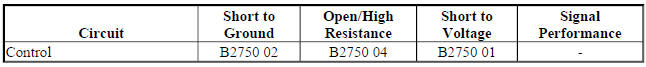
DTC B2750
Horn Relay Secondary Circuit
For symptom byte information refer to: Symptom Byte List
Diagnostic Fault Information
Circuit/System Description
The Body Control Module provides a ground for the Horn printed circuit board relay within the underhood fuse block. The underhood fuse block will then provide B+ voltage to the horn control circuit, sounding the horn.
Conditions for Running the DTC
When the horn output is actively being requested by the Body Control Module.
Conditions for Setting the DTC
B2750 01
The Body Control Module detects a short to voltage in the horn relay control circuit.
B2750 02
The Body Control Module detects a short to ground in the horn relay control circuit.
B2750 04
The Body Control Module detects an open/high resistance in the horn relay control circuit.
Action Taken When the DTC Sets
B2750 01, B2750 04
The Body Control Module will command the horn when requested but the horn will be inoperative.
B2750 02
The horn will sound continuously until the horn is disconnected or when the horn overheats and becomes inoperative.
Conditions for Clearing the DTC
- The DTC clears when the fault is no longer detected.
- The current DTC will become history when the request for the output is removed.
- The history DTC will clear after 50 consecutive fault-free ignition cycles have occurred.
Reference Information
Schematic Reference
Horn Schematics (Encore), Horn Schematics (Trax)
Connector End View Reference
WIRING SYSTEMS AND POWER MANAGEMENT - COMPONENT CONNECTOR END VIEWS - INDEX - ENCORE WIRING SYSTEMS AND POWER MANAGEMENT - COMPONENT CONNECTOR END VIEWS - INDEX - TRAX
Description and Operation
Horns System Description and Operation
Electrical Information Reference
- Circuit Testing
- Connector Repairs
- Testing for Intermittent Conditions and Poor Connections
- Wiring Repairs
Scan Tool Reference
Control Module References for scan tool information
Circuit/System Verification
- Ignition ON.
- Verify the operation of the P12 Horn when commanding the Horn Relay On and Off with a scan tool.
- If the P12 Horn is always ON or always OFF
Refer to Circuit/System Testing.
- If the P12 Horn turns ON and OFF
- All OK.
Circuit/System Testing
- Ignition OFF, disconnect the X1 harness connector at the X50A Fuse Block-Underhood, ignition ON.
- Verify the P12 Horn is not activated.
- If the P12 Horn is activated
- Ignition OFF, disconnect the harness connector at the P12 Horn, ignition ON.
- Test for less than 1 V between the control circuit terminal 2 and ground.
- If 1 V or greater, repair the short to voltage on the circuit.
- If less than 1 V, test or replace the P12 Horn.
- If the P12 Horn is not activated
- Connect a 15A fused jumper wire between the control circuit terminal D4 and B+.
- Verify the P12 Horn activates.
If the P12 Horn does not activate
- Ignition OFF, remove the jumper wire, disconnect the harness connector at the P12 Horn, ignition ON.
- Test for infinite resistance between the control circuit and ground.
- If less than Infinite resistance, repair the short to ground on the circuit.
- If infinite resistance
- Test for less than 2 ohms in the control circuit end to end.
- If 2 ohms or greater, repair the open/high resistance in the circuit.
- If less than 2 ohms, test or replace the P12 Horn.
- If the P12 Horn activates
- Ignition OFF, connect the X1 harness connector at the X50A Fuse Block-Underhood. Disconnect the X5 harness connector at the K9 Body Control Module, ignition ON.
- Verify the P12 Horn is not activated.
- If the P12 Horn is activated
- Ignition OFF, disconnect the X2 harness connector at the X50A Fuse Block-Underhood.
- Test for infinite resistance between the control circuit terminal 19 X5 at the K9 Body Control Module and ground.
- If less than Infinite resistance, repair the short to ground on the circuit.
- If infinite resistance, test or replace the X50A Fuse Block-Underhood.
- If the P12 Horn is not activated
- Connect a 3 A fused jumper wire between the control circuit terminal 19 and ground.
- Verify the P12 Horn activates.
- If the P12 Horn does not activate
- Ignition OFF, remove the jumper wire, disconnect the X2 harness connector at the X50A Fuse Block-Underhood, ignition ON.
- Test for less than 1 V between the control circuit terminal 19 X5 at the K9 Body Control Module and ground.
- If 1 V or greater, repair the short to voltage on the circuit.
- If less than 1 V
- Test for less than 2 ohms in the control circuit end to end.
- If 2 ohms or greater, repair the open/high resistance in the circuit.
- If less than 2 ohms, test or replace the X50A Fuse Block-Underhood.
- If the P12 Horn activates
- Replace the K9 Body Control Module.
Repair Instructions
Perform the Diagnostic Repair Verification after completing the repair.
- Front Compartment Fuse Block Replacement
- Control Module References for Body Control Module replacement, programming and setup
SYMPTOMS - HORNS
IMPORTANT: The following steps must be completed before using the symptom tables:
- Perform Diagnostic System Check - Vehicle , before using the symptom tables in order to verify that all of the following are true:
- There are no DTCs set
- The control modules can communicate via the serial data link
- Review the system operation in order to familiarize yourself with the system functions. Refer to Horns System Description and Operation.
Visual/Physical Inspection
- Inspect for aftermarket devices which could affect the operation of the horn system. Refer to Checking Aftermarket Accessories .
- Inspect the easily accessible or visible system components for obvious damage or conditions which could cause the symptom.
- Perform the following if a horn buzzes or has a harsh tone.
- Inspect for debris in the joint where the horn fastens to the vehicle.
- Test the torque of the horn mounting hardware. The horn mounting hardware should be tightened to a torque of 10 N.m (7 lb ft).
Intermittent
Faulty electrical connections or wiring may be the cause of intermittent conditions. Refer to Testing for Intermittent Conditions and Poor Connections
Symptom List
Refer to a symptom diagnostic procedure Horns Malfunction in order to diagnose the symptom.
READ NEXT:
 Horns malfunction
Diagnostic Instructions
Perform the Diagnostic System Check - Vehicle prior to using this
diagnostic procedure.
Review Strategy Based Diagnosis for an overview of the diagnostic
approach.
Diag
Horns - Repair instructions
HORN REPLACEMENT
Fig. 3: Horn
Horn Replacement
STEERING WHEEL HORN CONTACT REPLACEMENT (ENCORE)
Fig. 4: Steering Wheel Horn Contact (Encore)
Steering Wheel Horn Contact Replacement (Encore)
Horns - Description and operation
HORNS SYSTEM DESCRIPTION AND OPERATION
System Description
The horn system consists of the following components:
HORN fuse
Underhood fuse block (contains PCB horn relay)
Horn switch
Horn-low note
SEE MORE:
DTC B302A: Mobile telephone communications interface requested
immobilization
Diagnostic Instructions
Perform the Diagnostic System Check - Vehicle prior to using this
diagnostic procedure.
Review Strategy Based Diagnosis for an overview of the diagnostic
approach.
Diagnostic Procedure Instructions provides an overview of each
diagnostic category.
DTC Descriptor
DT
Master cylinder replacement
Removal Procedure
WARNING: Refer to Brake Fluid Irritant Warning .
CAUTION: Refer to Brake Fluid Effects on Paint and Electrical
Components Caution .
Place the ignition switch in the OFF position.
Remove the battery. Refer to Battery Replacement .
Disconnect the brake fluid level indicator swit
