Chevrolet Trax: Horns - Description and operation
HORNS SYSTEM DESCRIPTION AND OPERATION
System Description
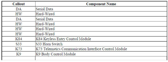
The horn system consists of the following components:
- HORN fuse
- Underhood fuse block (contains PCB horn relay)
- Horn switch
- Horn-low note
- Horn-high note
- Body control module (BCM)
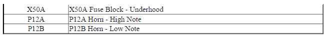
14 Horns Block Diagram
Fig. 6: 14 Horns Block Diagram
System Operation
The vehicle horn system is activated under the following conditions:
- When the horn switch is depressed
- The BCM commands the horns ON under any of the following conditions:
- When the content theft deterrent system detects a vehicle intrusion-For further information refer to Theft Systems Description and Operation .
- When the panic button is depressed on the remote control door lock transmitter-For further information refer to Keyless Entry System Description and Operation .
- When the keyless entry system is used to lock the vehicle, a horn chirp may sound to notify the driver that the vehicle has been locked. The notification feature may be enabled or disabled through personalization. For further information refer to Keyless Entry System Description and Operation .
- When the OnStar system is used to sound the horns if equipped-For further information, refer to OnStar Description and Operation
Circuit Operation
Battery positive voltage is applied at all times to the horn relay coil and the horn relay switch. Pressing either of the horn switches applies ground to the horn relay control circuit. The BCM may also apply ground to the horn relay control circuit as described above. When the horn relay control circuit is grounded, the horn relay is energized and battery positive voltage is applied to the horns through the horn control circuit. The horns sound as long as ground is applied to the horn relay control circuit.
READ NEXT:
 Immobilizer
Schematic wiring diagrams
IMMOBILIZER WIRING SCHEMATICS (ENCORE)
Immobilzer System
Fig. 1: Immobilzer System
IMMOBILIZER WIRING SCHEMATICS (TRAX)
Immobilzer System
Fig. 2: Immobilzer System
DTC B2955: Security sensor data circuit
DIAGNOSTIC CODE INDEX
DTC B2955: SECURITY SENSOR DATA CIRCUIT
Diagnostic Instructions
Perform the Diagnostic System Check - Vehicle prior to using this
diagnostic procedure.
Review Strategy B
SEE MORE:
Connections
The required specific Onstar
subscription plan includes the
services that follow to help
customers stay connected.
For coverage maps
WiFi Connectivity (If Equipped)
The vehicle has a WiFi hotspot that
provides a high-speed, wireless
Internet connection to connect
multiple mobile devices (data plan
Rear disc brake pads replacement
Removal Procedure
WARNING: Refer to Brake Dust Warning .
Inspect the fluid level in the brake master cylinder reservoir.
If the brake fluid level is midway between the maximum-full point and
the minimum allowable level, no
brake fluid needs to be removed before proceeding.
If the brake fluid
