Chevrolet Trax: Horns malfunction
Diagnostic Instructions
- Perform the Diagnostic System Check - Vehicle prior to using this diagnostic procedure.
- Review Strategy Based Diagnosis for an overview of the diagnostic approach.
- Diagnostic Procedure Instructions provides an overview of each diagnostic category.
Diagnostic Fault Information
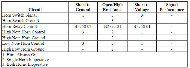
Circuit/System Description
The body control module monitors the horn switch signal circuit, when the horn pad is pressed, the body control module detects the drop in the horn switch signal circuit and provides a ground for the horn printed circuit board relay within the underhood fuse block. The underhood fuse block will then provide B+ voltage to the horn control circuit, sounding the horns
Diagnostic Aids
A short to ground in the horn relay control circuit or a short to voltage in the horn control circuit will cause the horns to sound continuously until the horns overheat and become inoperative.
Rotate the steering wheel while pressing the horn pad to identify intermittent and poor connections within the steering column.
If diagnosing a Horn- Poor Tone condition, inspect the following:
- Debris or water in the horn assembly
- Proper horn mounting hardware torque-Refer to Fastener Tightening Specifications.
- Debris in the joint where the horns attach to the vehicle
- Debris in direct contact with the horn
- Vehicle components vibrating while the horn is sounding
Reference Information
Schematic Reference
Horn Schematics (Encore), Horn Schematics (Trax)
Connector End View Reference
WIRING SYSTEMS AND POWER MANAGEMENT - COMPONENT CONNECTOR END VIEWS - INDEX - ENCORE WIRING SYSTEMS AND POWER MANAGEMENT - COMPONENT CONNECTOR END VIEWS - INDEX - TRAX
Description and Operation
Horns System Description and Operation
Electrical Information Reference
- Circuit Testing
- Connector Repairs
- Testing for Intermittent Conditions and Poor Connections
- Wiring Repairs
Scan Tool Reference
Control Module References for scan tool information
Circuit/System Verification
- Ignition ON.
- Verify the scan tool Horn Command Relay parameter changes between Active and Inactive when pressing and releasing the horn pad.
- If the parameter does not change
Refer to Circuit/System Testing - Horn Switch Malfunction
- If the parameter changes
- Verify the P12A Horn-High Note and P12B Horn-Low Note turns ON and OFF and emit a clear and even tone when commanding the Horn Relay On and Off with a scan tool.
- If both P12A Horn-High Note and P12B Horn-Low Note do not turn ON and OFF
Refer to Circuit/System Testing - Horns or Horn Command Malfunction.
- If a single P12 Horn does not turn ON or OFF or if the sound emitted is not clear and even
Refer to Circuit/System Testing - Horn - Poor Tone.
- If the horns turn ON and OFF and emit a even and clear tone
- All OK.
Circuit/System Testing
Horn Switch Malfunction
NOTE: Refer to SIR Service Precautions
- Ignition OFF, disconnect the X1 harness connector at the X85 Steering Wheel Air Bag Coil. Ignition ON
- Verify the scan tool Horn Command Relay parameter is Inactive.
- If not Inactive
- Ignition OFF, disconnect the harness connector at the K9 Body Control Module.
- Test for infinite resistance between the signal circuit terminal 1 and ground.
- If less than infinite resistance, repair the short to ground on the circuit.
- If infinite resistance, replace the K9 Body Control Module.
- If Inactive
- Install a 3 A fused jumper wire between the signal circuit terminal 1 and ground.
- Verify the scan tool Horn Command Relay parameter is Active.
- If not Active
- Ignition OFF, remove the jumper wire, disconnect the harness connector at the K9 Body Control Module, ignition ON.
- Test for less than 1 V between the signal circuit and ground.
- If 1 V or greater, repair the short to voltage on the circuit.
- If less than 1 V
- Test for less than 2 ohms in the signal circuit end to end.
- If 2 ohms or greater, repair the open/high resistance in the circuit.
- If less than 2 ohms, replace the K9 Body Control Module.
- If Active
- Test or replace the S33 Horn Switch.
Horns or Horn Command Malfunction
- Ignition OFF, disconnect the harness connector at the appropriate P12 Horn.
- Connect a test lamp between the control circuit terminal 2 and ground, ignition ON.
- Verify the test lamp does not turn ON and OFF when commanding the Horn Relay On and Off with a scan tool.
- If the test lamp turns ON and OFF
Test or replace the P12 Horn.
- If the test lamp does not turn ON and OFF
- Ignition OFF, connect the harness connector at the P12 Horn. Disconnect the X1 harness connector at the X50A Fuse Block-Underhood, ignition ON.
- Verify the P12A Horn-High Note and P12B Horn-Low Note are not activated.
- If the P12A Horn-High Note and P12B Horn-Low Note is activated
- Ignition OFF, disconnect the harness connector at the P12A Horn-High Note and P12B Horn-Low Note, ignition ON.
- Test for less than 1 V between the control circuit terminal 2 and ground.
- If 1 V or greater, repair the short to voltage on the circuit.
- If less than 1 V, test or replace the P12A Horn-High Note and P12B Horn-Low Note.
- If the P12A Horn-High Note and P12B Horn-Low Note is not activated
- Connect a 15 A fused jumper wire between the control circuit terminal listed below and B+.
- Control circuit terminal D4
- Control circuit terminal C6
- Verify the P12A Horn-High Note or P12B Horn-Low Note activates.
- If the P12A Horn-High Note and P12B Horn-Low Note does not activate
- Ignition OFF, remove the jumper wire, disconnect the harness connector at the P12 Horn, ignition ON.
- Test for infinite resistance between the control circuit and ground.
- If less than Infinite resistance, repair the short to ground on the circuit.
- If infinite resistance
- Test for less than 2 ohms in the control circuit end to end.
- If 2 ohms or greater, repair the open/high resistance in the circuit.
- If less than 2 ohms, test or replace the P12 Horn.
- If the P12A Horn-High Note and P12B Horn-Low Note activates
- Ignition OFF, connect the X1 harness connector at the X50A Fuse Block-Underhood. Disconnect the X5 harness connector at the K9 Body Control Module, ignition ON.
- Verify the P12A Horn-High Note and P12B Horn-Low Note are not activated.
- If the P12A Horn-High Note and P12B Horn-Low Note is activated
- Ignition OFF, disconnect the X2 harness connector at the X50A Fuse Block-Underhood.
- Test for infinite resistance between the control circuit terminal 19 X5 at the K9 Body Control Module and ground.
- If less than Infinite resistance, repair the short to ground on the circuit.
- If infinite resistance, replace the X50A Fuse Block-Underhood.
- If the P12A Horn-High Note and P12B Horn-Low Note are not activated
- Connect a 3 A fused jumper wire between the control circuit terminal 19 and ground.
- Verify the P12A Horn-High Note and P12B Horn-Low Note activates.
- If the P12 Horn does not activate
- Ignition OFF, remove the jumper wire, disconnect the X2 harness connector at the X50A Fuse Block-Underhood, ignition ON.
- Test for less than 1 V between the control circuit terminal 19 X5 at the K9 Body Control Module and ground.
- If 1 V or greater, repair the short to voltage on the circuit.
- If less than 1 V
- Test for less than 2 ohms in the control circuit end to end.
- If 2 ohms or greater, repair the open/high resistance in the circuit.
- If less than 2 ohms, replace the X50A Fuse Block-Underhood.
- If the P12A Horn-High Note and P12B Horn-Low Note activates
- Replace the K9 Body Control Module.
Horn - Poor Tone
- Ignition OFF and all vehicle systems OFF, disconnect the harness
connector at the appropriate P12 Horn.
It may take up to 2 minutes for all vehicle systems to power down.
- Test for less than 1 ohms between the ground circuit terminal 1 and ground.
- If 1 ohms or greater
- Ignition OFF.
- Test for less than 2 ohms in the ground circuit end to end.
- If 2 ohms or greater, repair the high resistance in the circuit.
- If less than 2 ohms, repair high resistance in the ground connection.
- If less than 1 ohms
- Ignition OFF, disconnect the X1 harness connector at the X50A Fuse Block-Underhood.
- Test for less than 2 ohms between the control circuit terminals listed below:
- P12B Horn-Low Note control circuit terminal 2 and X50A Fuse Block-Underhood control circuit terminal D4 X1
- P12A Horn-High Note control circuit terminal 2 and X50A Fuse Block-Underhood control circuit terminal C6 X1
- If 2 ohms or greater
Repair the high resistance in the control circuit.
- If less than 2 ohms
- Test or replace the P12 Horn.
Component Testing
Horn Test
- Ignition OFF, disconnect the harness connector at the appropriate P12 Horn.
- Install a 15 A fused jumper wire between the control terminal 2 and 12 V. Install a jumper wire between the ground terminal 1 and ground.
- Verify the P12 Horn turns ON and OFF
- If the P12 Horn does not turn ON and OFF
Replace the P12 Horn.
- If the P12 Horn turns ON and OFF
- All OK
Repair Instructions
Perform the Diagnostic Repair Verification after completing the repair.
- Steering Wheel Horn Contact Replacement (Encore), Steering Wheel Horn Contact Replacement (Trax)
- Horn Replacement
- Front Compartment Fuse Block Replacement
- Control Module References for body control module replacement, programming and setup
READ NEXT:
 Horns - Repair instructions
HORN REPLACEMENT
Fig. 3: Horn
Horn Replacement
STEERING WHEEL HORN CONTACT REPLACEMENT (ENCORE)
Fig. 4: Steering Wheel Horn Contact (Encore)
Steering Wheel Horn Contact Replacement (Encore)
Horns - Description and operation
HORNS SYSTEM DESCRIPTION AND OPERATION
System Description
The horn system consists of the following components:
HORN fuse
Underhood fuse block (contains PCB horn relay)
Horn switch
Horn-low note
Immobilizer
Schematic wiring diagrams
IMMOBILIZER WIRING SCHEMATICS (ENCORE)
Immobilzer System
Fig. 1: Immobilzer System
IMMOBILIZER WIRING SCHEMATICS (TRAX)
Immobilzer System
Fig. 2: Immobilzer System
SEE MORE:
Repair instructions
BODY WATERLEAK REPAIR
Fig. 6: Cutting Out A Portion Of The Adhesive Caulking (1 Of 2)
WARNING: If the vehicle interior is exposed to moisture and becomes
soaked up to
the level of the sensing and diagnostic module (SDM), the SDM and SDM
harness connector must be replaced. The SDM could be activat
DTC P0133, P013A, P013B, P013E, P013F, P015A, P015B, P2270, OR P2271 (LUV)
Diagnostic Instructions
Perform the Diagnostic System Check - Vehicle prior to using this
diagnostic procedure.
Review Strategy Based Diagnosis for an overview of the diagnostic
approach.
Diagnostic Procedure Instructions provide an overview of each
diagnostic category.
DTC Descriptors
DT
