Chevrolet Trax: Fog lamp aiming
Preparation Procedure
NOTE:
Horizontal aim is not adjustable on this vehicle. Adjust the fog lamp as required using the adjusting screw above the projector lens on the outside of the front bumper fascia. Prior to aiming the fog lamps, perform the following steps:
- Completely assemble all of the components on the vehicle.
- Place the vehicle on a level surface.
- Stop all unnecessary operations or work that could affect the ride height of the vehicle.
- Close the doors and verify that the luggage compartment is empty.
- Stabilize the suspension by rocking the vehicle sideways.
- Ensure that the fuel level is full.
- Ensure that the tires are inflated to the proper pressure.
- Ensure that the driver or a similar weight, approximately 75 kg (165 lb), is in the vehicle driver seat.
Aiming Procedure
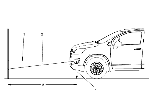
Fig. 41: Headlamp Aiming Distances
- Park the vehicle 7.6 m (25 ft) away from the target screen (a).
- Measure the distance from the center of the fog lamp to the ground line (b).
- Using this measurement, mark the horizontal centerline (1) of the fog lamp on the target screen directly in front of the vehicle.
- Turn ON the fog lamps.
- The top of the fog lamp beam image (2) on the target screen should be 102 mm (4 in) below the center of the fog lamp lens height (1).
- Adjust the fog lamp as required using the adjusting screw above the projector lens on the outside of the front bumper fascia.
- After the adjustments are made, turn OFF the fog lamps.
FRONT TURN SIGNAL LAMP BULB REPLACEMENT (LEFT HAND)
.gif)
Fig. 42: Front Turn Signal Lamp Bulb (Left Hand)
Front Turn Signal Lamp Bulb Replacement (Left hand)
.jpg)
FRONT TURN SIGNAL LAMP BULB REPLACEMENT (RIGHT HAND)
.gif)
Fig. 43: Front Turn Signal Lamp Bulb (Right Hand)
Front Turn Signal Lamp Bulb Replacement (Right Hand)
.jpg)
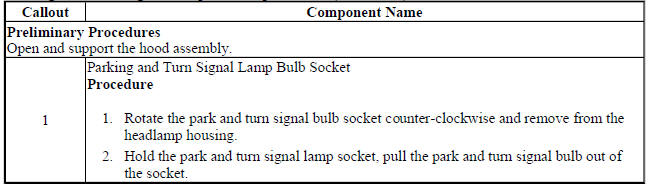
PARKING AND TURN SIGNAL LAMP BULB REPLACEMENT (LEFT HAND)
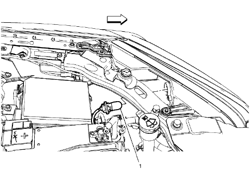
Fig. 44: Parking and Turn Signal Lamp Bulb (Left Hand)
Parking and Turn Signal Lamp Bulb Replacement (Left Hand)
PARKING AND TURN SIGNAL LAMP BULB REPLACEMENT (RIGHT HAND)
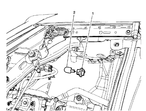
Fig. 45: Parking and Turn Signal Lamp Bulb (Right Hand)
Parking and Turn Signal Lamp Bulb Replacement (Right Hand)
.jpg)
HIGH MOUNT STOP LAMP REPLACEMENT
.gif)
Fig. 46: High Mount Stop Lamp
High Mount Stop Lamp Replacement
.jpg)
CARGO LAMP REPLACEMENT
.gif)
Fig. 47: Cargo Lamp
Cargo Lamp Replacement
.jpg)
CARGO CENTER COURTESY LAMP BULB REPLACEMENT
.gif)
Fig. 48: Cargo Center Courtesy Lamp Bulb
Cargo Center Courtesy Lamp Bulb Replacement
.jpg)
BACKUP LAMP BULB REPLACEMENT (TRAX)
.gif)
Fig. 49: Backup Lamp Bulb (Trax)
Backup Lamp Bulb Replacement (Trax)
.jpg)
BACKUP LAMP BULB REPLACEMENT (ENCORE)
.gif)
Fig. 50: Backup Lamp Bulb (Encore)
Backup Lamp Bulb Replacement (Encore)
.jpg)
REAR LICENSE PLATE LAMP REPLACEMENT
.gif)
Fig. 51: Rear License Plate Lamp
Rear License Plate Lamp Replacement
.jpg)
REAR LICENSE PLATE LAMP BULB REPLACEMENT
.gif)
Fig. 52: Rear License Plate Lamp Bulb
Rear License Plate Lamp Bulb Replacement
.jpg)
REAR LICENSE PLATE LAMP WIRING HARNESS REPLACEMENT
.gif)
Fig. 53: Rear License Plate Lamp Wiring Harness
Rear License Plate Lamp Wiring Harness Replacement
.jpg)
TAIL LAMP REPLACEMENT (TRAX)
.gif)
Fig. 54: Tail Lamp (Trax)
Tail Lamp Replacement (Trax)
.jpg)
TAIL LAMP REPLACEMENT (ENCORE)
.gif)
Fig. 55: Tail Lamp (Encore)
Tail Lamp Replacement (Encore)
.jpg)
.jpg)
STOP AND TAIL LAMP BULB REPLACEMENT (TRAX)
.gif)
Fig. 56: Stop and Tail Lamp Bulb (Trax)
Stop and Tail Lamp Bulb Replacement (Trax)
.jpg)
.jpg)
STOP AND TAIL LAMP BULB REPLACEMENT (ENCORE)
.gif)
Fig. 57: Stop And Tail Lamp Bulb (Encore)
Stop and Tail Lamp Bulb Replacement (Encore)
.jpg)
.gif)
REAR TURN SIGNAL LAMP BULB REPLACEMENT (TRAX)
.gif)
Fig. 58: Rear Turn Signal Lamp Bulb (Trax)
Rear Turn Signal Lamp Bulb Replacement (Trax)
.jpg)
REAR TURN SIGNAL LAMP BULB REPLACEMENT (ENCORE)
.gif)
Fig. 59: Rear Turn Signal Lamp Bulb (Encore)
Rear Turn Signal Lamp Bulb Replacement (Encore)
.jpg)
