Chevrolet Trax: Rear wheel drive shaft replacement
Special Tools
CH-45859 Axle Remover
For regional equivalent tools, refer to Special Tools.
Removal Procedure
- Raise and support the vehicle. Refer to Lifting and Jacking the Vehicle .
- Remove the tire and wheel assembly. Refer to Tire and Wheel Removal and Installation .
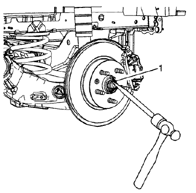
Fig. 30: Removing Stake From Rear Wheel Drive Shaft
- Using a hammer and a punch, remove the stake (1) from the rear wheel drive shaft.
- With the aid of an assistant, apply the brakes.
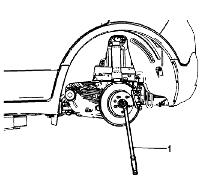
Fig. 31: Loosening Wheel Drive Shaft Nut
CAUTION: Make sure that the wheel drive shaft nut is fully un-staked to avoid damage to the wheel drive shaft threads during the removal of the wheel drive shaft nut. Failure to follow these instructions could result in wheel, nut, and/or stud damage.
- Using a breaker bar and the proper size socket (1), loosen the wheel drive shaft nut.
- Remove and relocate the rear brake caliper assembly. Refer to Rear Brake Caliper Replacement
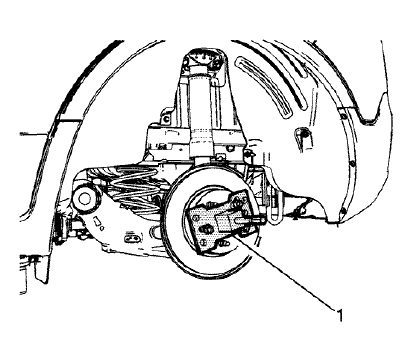
Fig. 32: Separating Wheel Drive Shaft From Wheel Bearing/Hub
- Using the CH-45859 remover (1), separate the wheel drive shaft from the wheel bearing/hub assembly.
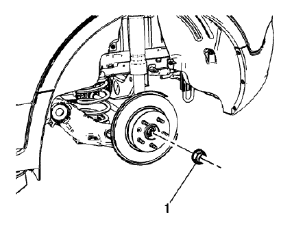
Fig. 33: Wheel Drive Shaft Nut
- Remove and discard the wheel drive shaft nut (1) from the wheel drive shaft. Replace with NEW nut only.
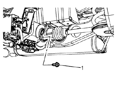
Fig. 34: Wheel Drive Shaft Bolts
- Remove the 3 wheel drive shaft bolts (1).
.gif)
Fig. 35: Wheel Drive Shaft
- Remove the wheel drive shaft (1).
Installation Procedure
.gif)
Fig. 36: Wheel Drive Shaft
- Position the wheel drive shaft (1) in the vehicle.
.gif)
Fig. 37: Wheel Drive Shaft Bolts
CAUTION: Refer to Fastener Caution .
- Install and tighten the 3 wheel drive shaft bolts (1) to 58 (43 lb ft)
.gif)
Fig. 38: Wheel Drive Shaft Nut
- Install the wheel drive shaft nut (1).
- Install the rear brake caliper assembly. Refer to Rear Brake Caliper Replacement
- With the aid of an assistant, apply the brakes
.gif)
Fig. 39: Torque Wrench And Wheel Drive Shaft Nut
- Using the proper size socket and torque wrench (1), tighten the wheel drive shaft nut to:
- First Pass 50 (37 lb ft)
- Final Pass plus 60 degrees
.gif)
Fig. 40: Splitting Center Of Wheel Drive Shaft Nut
NOTE: Evenly split the center of the wheel drive shaft nut (2) and ensure that it is fully staked. Each side of the stake should be in contact and approximately 45 degrees to each side of the slot in the wheel drive shaft.
- Using the punch (1) and hammer, stake the wheel drive shaft nut (2) collar into the slot on the wheel drive shaft.
- Install the tire and wheel assembly. Refer to Tire and Wheel Removal and Installation .
- Remove the support and lower the vehicle.

