Chevrolet Trax: Rear side door outer panel replacement
Chevrolet Trax (2013-2022) Workshop Manual / Accessories & Equipment / Collision Repair / Collision repair - Repair instructions / Rear side door outer panel replacement
Special Tools
- BO-6392 Flanging Tool Kit
- BO-6396 Bonding Pliers
For equivalent regional tools, refer to Special Tools.
NOTE: According to different corrosion warranties, only the regional mandatory joining methods are allowed.
Removal Procedure
WARNING: Refer to Glass and Sheet Metal Handling Warning .
- Disable the SIR System. Refer to SIR Disabling and Enabling .
- Disconnect the negative battery cable. Refer to Battery Negative Cable Disconnection and Connection .
- Remove the rear side door. Refer to Rear Side Door Replacement .
- Remove the rear side door outside handle. Refer to Rear Side Door Outside Handle Replacement .
- Remove the sealers and anti-corrosion materials from the repair area, as necessary. Refer to Anti- Corrosion Treatment and Repair (Base)
.gif)
Fig. 89: Grinding Edges Of Rear Side Door Outer Panel
- Grind the edges of the rear side door outer panel (1) to separate the outer door panel from the door shell.
.gif)
Fig. 90: Rear Side Door Outer Door Panel
- Remove the rear side door outer door panel (1).
- Remove the sealers and anti-corrosion materials from the repair area, as necessary. Refer to Anti- Corrosion Treatment and Repair (Base) .
- Straighten the edges of the door shell.
Installation Procedure
- Align the rear side door outer panel.
- Verify the fit of the rear side door outer panel.
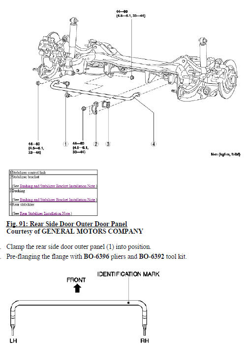
Fig. 92: Rear Side Door Outer Door Panel Hem Flanges
- Continue to hammer in stages along the hem flanges (1).
- Apply the sealers and anti-corrosion materials to the repair area, as necessary. Refer to Anti-Corrosion Treatment and Repair (Base) .
- Install the rear side door outside handle. Refer to Rear Side Door Outside Handle Replacement .
- Install the rear side door. Refer to Rear Side Door Replacement .
- Paint the repaired area. Refer to Basecoat/Clearcoat Paint Systems .
- Install all related panels and components.
- Connect the negative battery cable. Refer to Battery Negative Cable Disconnection and Connection .
- Enable the SIR system. Refer to SIR Disabling and Enabling
READ NEXT:
 Rear compartment floor panel replacement
Removal Procedure
WARNING: Refer to Approved Equipment for Collision Repair Warning .
WARNING: Refer to Glass and Sheet Metal Handling Warning .
Disable the SIR system. Refer to SIR Disabling and En
Rear wheelhouse outer panel replacement
Removal Procedure
WARNING: Refer to Approved Equipment for Collision Repair Warning .
WARNING: Refer to Glass and Sheet Metal Handling Warning
Disable the SIR system. Refer to SIR Disabling and Enab
Quarter outer panel sectioning
NOTE: According to different corrosion warranties, only the
regional mandatory joining
methods are allowed.
Removal Procedure
WARNING: Refer to Approved Equipment for Collision Repair Warning .
WARNI
SEE MORE:
Side object system malfunction
Diagnostic Instructions
Perform the Diagnostic System Check - Vehicle prior to using this
diagnostic procedure.
Review Strategy Based Diagnosis for an overview of the diagnostic
approach.
Diagnostic Procedure Instructions provides an overview of each
diagnostic category.
Diagnostic Fault
Smartphone Link (Stitcher)
Some images and explanations may
vary by phone operating systems,
versions, and/or application (App)
versions.
Using Stitcher
Install the Stitcher application on
the smartphone.
Connect the smartphone to the
infotainment system through the
USB port or Bluetooth wireless
technology.
iPhone:
© 2019-2025 Copyright www.chevtrax.com

