Chevrolet Trax Owners & Service Manuals

Chevrolet Trax: Input, reaction, and output carrier disassemble

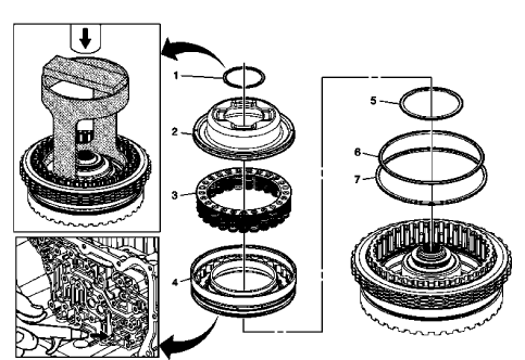
Fig. 24: Disassembled View Of Input, Reaction & Output Carrier

Courtesy of GENERAL MOTORS COMPANY

Input, Reaction, and Output Carrier Disassemble

Input, Reaction, and Output Carrier Disassemble

3-5-REVERSE AND 4-5-6 CLUTCH HOUSING DISASSEMBLE (6T40 - GEN 2)

Turbine Shaft, Reluctor Wheel and Piston Removal
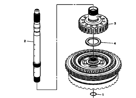
Fig. 25: Turbine Shaft, Reluctor Wheel And Piston

Turbine Shaft, Reluctor Wheel and Piston Removal

Turbine Shaft, Reluctor Wheel and Piston Removal

4-5-6 Clutch Plate Removal

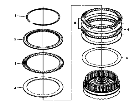
Fig. 26: 4-5-6 Clutch Plate Components

4-5-6 Clutch Plate Removal

4-5-6 Clutch Plate Removal

4-5-6 Clutch Piston Removal

Fig. 27: 4-5-6 Clutch Piston Components

4-5-6 Clutch Piston Removal

4-5-6 Clutch Piston Removal

4-5-6 Clutch Piston Removal

Reluctor Wheel and Piston Removal

Fig. 28: Disassembled View Of Reluctor Wheel & Piston

Reluctor Wheel and Piston Removal

Reluctor Wheel and Piston Removal

Reluctor Wheel and Piston Removal

3-5 Reverse Clutch Plate Removal

Fig. 29: 3-5 Reverse Clutch Plate Components

3-5 Reverse Clutch Plate Removal

3-5 Reverse Clutch Plate Removal

3-5 Reverse Clutch Plate Removal

3-5-REVERSE AND 4-5-6 CLUTCH HOUSING ASSEMBLE (6T40 - GEN 2)

4-5-6 Clutch Piston Installation

Fig. 30: 4-5-6 Clutch Piston Components

4-5-6 Clutch Piston Installation

4-5-6 Clutch Piston Installation

4-5-6 Clutch Piston Installation

4-5-6 Clutch Fluid Dam Installation

Fig. 31: 4-5-6 Clutch Fluid Dam

4-5-6 Clutch Fluid Dam Installation

4-5-6 Clutch Fluid Dam Installation

4-5-6 Clutch Fluid Dam Installation

3-5 Reverse Clutch Plates Installation
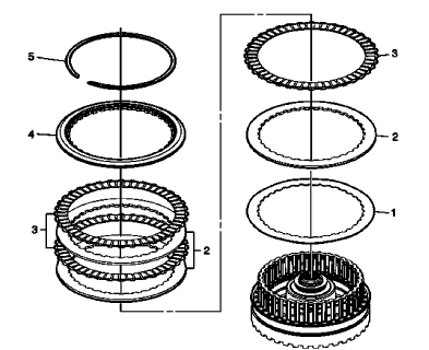
Fig. 32: 3-5 Reverse Clutch Plates

3-5 Reverse Clutch Plates Installation

3-5 Reverse Clutch Plates Installation

Reluctor Wheel and Piston Installation

Fig. 33: Exploded View Of Reluctor Wheel & Piston

Reluctor Wheel and Piston Installation

Reluctor Wheel and Piston Installation

Reluctor Wheel and Piston Installation

4-5-6 Clutch Plates Installation

Fig. 34: 4-5-6 Clutch Plates

4-5-6 Clutch Plates Installation

4-5-6 Clutch Plates Installation

Turbine Shaft Installation

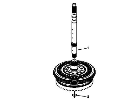
Fig. 35: View Of Turbine Shaft

Turbine Shaft Installation

Turbine Shaft Installation

INPUT, REACTION, AND OUTPUT CARRIER ASSEMBLE (GEN 2)
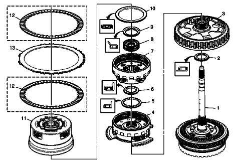
Fig. 36: Input, Reaction, and Output Carrier Components (Gen 2)

Input, Reaction, and Output Carrier Assemble (Gen 2)

Input, Reaction, and Output Carrier Assemble (Gen 2)

Input, Reaction, and Output Carrier Assemble (Gen 2)

3-5-REVERSE AND 4-5-6 CLUTCH HOUSING, AND INPUT, REACTION, AND OUTPUT CARRIER INSTALLATION
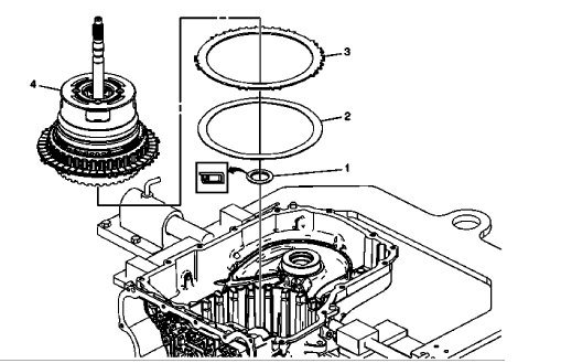
Fig. 37: View Of 3-5-Reverse, 4-5-6 Clutch Housing, Input, Reaction & Output Carrier Components

3-5-Reverse and 4-5-6 Clutch Housing, and Input, Reaction, and Output Carrier Installation

3-5-Reverse and 4-5-6 Clutch Housing, and Input, Reaction, and Output Carrier Installation

LOW AND REVERSE CLUTCH ASSEMBLY AND LOW AND REVERSE CLUTCH PLATE INSTALLATION

Fig. 38: View Of Low and Reverse Clutch Assembly

Low and Reverse Clutch Assembly and Low and Reverse Clutch Plate Installation

Low and Reverse Clutch Assembly and Low and Reverse Clutch Plate Installation

Low and Reverse Clutch Assembly and Low and Reverse Clutch Plate Installation

    READ NEXT:

     Low and reverse and 1-2-3-4 clutch housing isassemble

    Low and Reverse Clutch Piston Removal Fig. 39: View Of Low & Reverse Clutch Piston Low and Reverse Clutch Piston Removal 1-2-3-4 Clutch Piston Removal Fig. 40: View Of 1-2-3-4 Clutch Pisto

     Drive sprocket, driven sprocket, and drive link cleaning and inspection

    Fig. 45: View Of Drive Sprocket, Driven Sprocket & Drive Link Drive Sprocket, Driven Sprocket, and Drive Link Cleaning and Inspection DRIVE AND DRIVEN SPROCKET, DRIVE LINK, AND PARK PAWL INSTA

     Control valve body assembly assemble (gen 2)

    Fig. 66: Control Valve Body And Components Control Valve Body Assembly Assemble (Gen 2) CONTROL VALVE BODY ASSEMBLY INSTALLATION Fig. 67: View Of Control Valve Body Assembly Attachments Control

    SEE MORE:

     Body hinge pillar lower reinforcement replacement

    Removal Procedure WARNING: Refer to Approved Equipment for Collision Repair Warning . Disable the SIR system. Refer to SIR Disabling and Enabling . Disconnect the negative battery cable. Refer to Battery Negative Cable Disconnection and Connection . Remove all related panels and components.

     Driver or passenger seat removal and installation

    SPECIFICATIONS FASTENER TIGHTENING SPECIFICATIONS Fastener Tightening Specifications DIAGNOSTIC INFORMATION AND PROCEDURES MANUAL SEAT ADJUSTER LOCKS BETWEEN LOCK POSITIONS Manual Seat Adjuster Locks Between Lock Positions SEATS - ADJUSTER TRACK LOCKS AHEAD OF OTHER TRACK Seats - Adjuster Track

    © 2019-2024 Copyright www.chevtrax.com