Chevrolet Trax: Drive sprocket, driven sprocket, and drive link cleaning and inspection
Fig. 45: View Of Drive Sprocket, Driven Sprocket & Drive Link
Drive Sprocket, Driven Sprocket, and Drive Link Cleaning and Inspection
.jpg)
DRIVE AND DRIVEN SPROCKET, DRIVE LINK, AND PARK PAWL INSTALLATION (6T40)
.gif)
Fig. 46: View Of Drive Sprocket, Driven Sprocket & Park Paw
Drive and Driven Sprocket, Drive Link, and Park Pawl Installation (6T40)
.jpg)
.jpg)
FRONT DIFFERENTIAL CARRIER CLEANING AND INSPECTION
.gif)
Fig. 47: View Of Front Differential Carrier
Front Differential Carrier Cleaning and Inspection
.jpg)
.jpg)
FRONT DIFFERENTIAL CARRIER INSTALLATION (6T40)
.gif)
Fig. 48: View Of Front Differential Carrier Components
Front Differential Carrier Installation (6T40)
.jpg)
TRANSMISSION FLUID PUMP, FRONT DIFFERENTIAL CARRIER BAFFLE, AND FRONT DIFFERENTIAL RING GEAR REMOVAL (6T40)
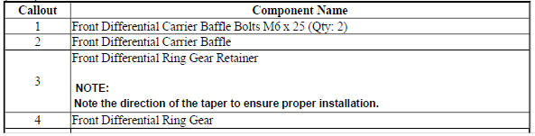
Fig. 49: View Of Transmission Fluid Pump, Front Differential Carrier Baffle &
Components
Transmission Fluid Pump, Front Differential Carrier Baffle, and Front Differential Ring Gear Removal (6T40)
.jpg)
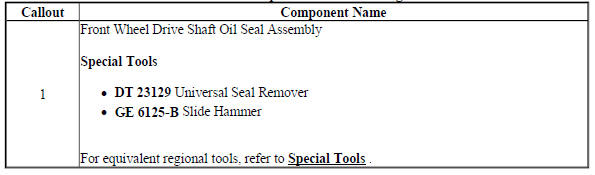
FRONT WHEEL DRIVE SHAFT SEAL REMOVAL - TORQUE CONVERTER HOUSING SIDE
Fig. 50: Front Wheel Drive Shaft Seal - Torque Converter Housing Side
Front Wheel Drive Shaft Seal Removal - Torque Converter Housing Side
FRONT DIFFERENTIAL CARRIER BEARING REMOVAL (AWD)
Fig. 51: Front Differential Carrier Bearing (AWD)
Front Differential Carrier Bearing Removal (AWD)
.jpg)
FRONT DIFFERENTIAL CARRIER BEARING INSTALLATION (AWD)
.gif)
Fig. 52: Front Differential Carrier Bearing (AWD)
Front Differential Carrier Bearing Installation (AWD)
.jpg)
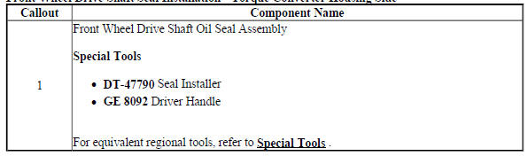
FRONT WHEEL DRIVE SHAFT SEAL INSTALLATION - TORQUE CONVERTER HOUSING SIDE
Fig. 53: Front Wheel Drive Shaft Seal - Torque Converter Housing Side
Front Wheel Drive Shaft Seal Installation - Torque Converter Housing Side
TORQUE CONVERTER HOUSING CLEANING AND INSPECTION
Fig. 54: Identifying Torque Converter Housing Inspection Areas
Torque Converter Housing Cleaning and Inspection
.jpg)
TRANSMISSION FLUID PUMP DISASSEMBLE (6T40)
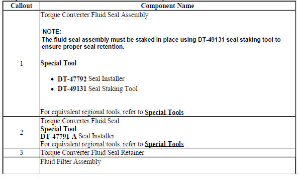
Fluid Filter Assembly and Torque Converter Fluid Seal Disassemble
.gif)
Fig. 55: View Of Fluid Filter Assembly & Torque Converter Fluid Seal
Fluid Filter Assembly and Torque Converter Fluid Seal Disassembl
.jpg)
.jpg)
Fluid Pump Disassemble
.gif)
Fig. 56: Transmission Fluid Pump & Components
Fluid Pump Disassemble
.jpg)
.jpg)
FLUID PUMP SELECTIVE MEASUREMENT
.gif)
Fig. 57: Measuring Fluid Pump Components
Fluid Pump Selective Measurement
.jpg)
.jpg)
TRANSMISSION FLUID PUMP ASSEMBLE (6T40)
Fluid Pump w/Valve Trains Assemble
.gif)
Fig. 58: Fluid Pump W/Valve Trains Assembly
Fluid Pump w/Valve Trains Assemble
.jpg)
Torque Converter Fluid Seal and Fluid Filter Assembly Assemble
Fig. 59: View Of Torque Converter Fluid Seal & Fluid Filter Assembly
Torque Converter Fluid Seal and Fluid Filter Assembly Assemble
.jpg)
TRANSMISSION FLUID PUMP, FRONT DIFFERENTIAL CARRIER BAFFLE, AND FRONT DIFFERENTIAL RING GEAR INSTALLATION (6T40)
Fig. 60: Identifying Transmission Fluid Pump, Front Differential Carrier
Baffle & Front Differential Ring Gear
Transmission Fluid Pump, Front Differential Carrier Baffle, and Front Differential Ring Gear Installation (6T40)
.jpg)
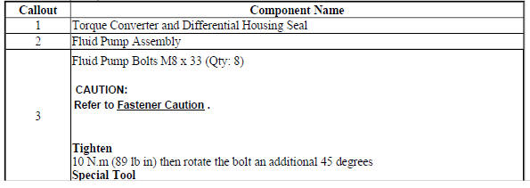
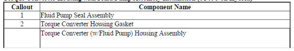
TORQUE CONVERTER HOUSING WITH FLUID PUMP ASSEMBLY INSTALLATION (6T40 NON HYBRID)
Fig. 61: Identifying Torque Converter Housing & Fluid Pump Assembly
Torque Converter Housing with Fluid Pump Assembly Installation (6T40 Non Hybrid)
.jpg)
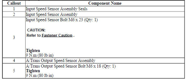
INPUT AND OUTPUT SPEED SENSOR INSTALLATION
Fig. 62: Identifying Input & Output Speed Sensor
Input and Output Speed Sensor Installation
CONTROL VALVE BODY ASSEMBLY DISASSEMBLE (GEN 2)
.gif)
Fig. 63: Control Valve Body (Gen 2)
Control Valve Body Assembly Disassemble (Gen 2)
.jpg)
CONTROL VALVE BODY CLEANING AND INSPECTION (GEN 2)
.gif)
Fig. 64: Control Valve Body Cleaning and Inspection (Gen 2)
Control Valve Body Cleaning and Inspection (Gen 2)
.jpg)
.jpg)
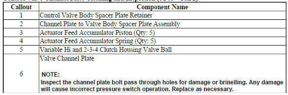
CONTROL VALVE CHANNEL PLATE CLEANING AND INSPECTION (6T40 - GEN 2)
.gif)
Fig. 65: Control Valve Channel Plate Cleaning and Inspection
Control Valve Channel Plate Cleaning and Inspection (6T40 - Gen 2)

READ NEXT:
 Control valve body assembly assemble (gen 2)
Fig. 66: Control Valve Body And Components
Control Valve Body Assembly Assemble (Gen 2)
CONTROL VALVE BODY ASSEMBLY INSTALLATION
Fig. 67: View Of Control Valve Body Assembly Attachments
Control
Manual shift detent lever with shaft position witch assembly replacement
Special Tools
DT-41229 Manual Shaft Pin Installer
For equivalent regional tools, refer to Special Tools .
Removal Procedure
Remove the engine coolant fan shroud. Refer to Engine Coolant Fan Shroud
SEE MORE:
Front wheel drive intermediate shaft replacement
Special Tools
J-41819 Input Shaft Seal Installer
DT-50937 Seal Protector
For equivalent regional tools, refer to Special Tools.
Removal Procedure
Remove the right drive shaft. Refer to Front Wheel Drive Shaft
Replacement - Right Side .
Fig. 12: Front Wheel Drive Intermediate Shaft Housing
DTC P018B-P018D (Chassis control module)
Diagnostic Instructions
Perform the Diagnostic System Check - Vehicle prior to using this
diagnostic procedure.
Review Strategy Based Diagnosis for an overview of the diagnostic
approach.
Diagnostic Procedure Instructions provides an overview of each
diagnostic category.
DTC Descriptors
D
