Chevrolet Trax Owners & Service Manuals

Chevrolet Trax: Control valve body assembly assemble (gen 2)
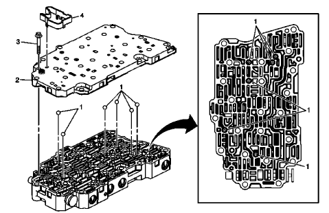
Fig. 66: Control Valve Body And Components

Control Valve Body Assembly Assemble (Gen 2)

Control Valve Body Assembly Assemble (Gen 2)

CONTROL VALVE BODY ASSEMBLY INSTALLATION
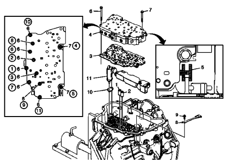
Fig. 67: View Of Control Valve Body Assembly Attachments

Control Valve Body Assembly Installation

Control Valve Body Assembly Installation

Control Valve Body Assembly Installation

CONTROL SOLENOID VALVE AND TRANSMISSION CONTROL MODULE ASSEMBLY INSTALLATION

Fig. 68: Identifying Control Solenoid Valve & TCM Bolt Tightening Sequence

Control Solenoid Valve and Transmission Control Module Assembly Installation

Control Solenoid Valve and Transmission Control Module Assembly Installation

Control Solenoid Valve and Transmission Control Module Assembly Installation

CONTROL VALVE BODY COVER INSTALLATION

Fig. 69: Identifying Control Valve Body Cover Bolt Tightening Sequence

Control Valve Body Cover Installation

Control Valve Body Cover Installation

Control Valve Body Cover Installation

TORQUE CONVERTER FLUID SEAL REPLACEMENT

Fig. 70: View Of Torque Converter Fluid Seal & Retainer

Torque Converter Fluid Seal Replacement

Torque Converter Fluid Seal Replacement

Torque Converter Fluid Seal Replacement

TORQUE CONVERTER INSTALLATION

Fig. 71: View Of Torque Converter

Torque Converter Installation

Torque Converter Installation

Torque Converter Installation

LIFT PLATE AND HOLDING FIXTURE REMOVAL

Fig. 72: Identifying Lift Plate & Holding Fixture

Lift Plate and Holding Fixture Removal

Lift Plate and Holding Fixture Removal

Lift Plate and Holding Fixture Removal

    READ NEXT:

     Repair instructions - on vehicle

     Manual shift detent lever with shaft position witch assembly replacement

    Special Tools DT-41229 Manual Shaft Pin Installer For equivalent regional tools, refer to Special Tools . Removal Procedure Remove the engine coolant fan shroud. Refer to Engine Coolant Fan Shroud

     Automatic transmission range selector lever replacement

    Removal Procedure Set the park brake and chock the wheels. Fig. 4: Automatic Transmission Range Selector Lever Cable Terminal And Shift Lever Pin Disconnect the transmission range selector lev

    SEE MORE:

     Rear axle replacement

    Special Tools CH 51035 Rear Axle Supporter Adapter DT 50187 Rear Axle Supporter For equivalent regional tools, refer to Special Tools . Removal Procedure Raise and support the vehicle. Refer to Lifting and Jacking the Vehicle . Remove the tires and wheel assembly. Refer to Tire and Wheel Re

     Schematic wiring diagrams

    SPECIFICATIONS FASTENER TIGHTENING SPECIFICATIONS Fastener Tightening Specifications SCHEMATIC WIRING DIAGRAMS MOVEABLE WINDOW WIRING SCHEMATICS (ENCORE) Front Windows Fig. 1: Front Windows Rear Windows Fig. 2: Rear Windows MOVEABLE WINDOW WIRING SCHEMATICS (TRAX) Front and Rear Power Windows

    © 2019-2024 Copyright www.chevtrax.com