Chevrolet Trax: Hazard lamps malfunction
Diagnostic Instructions
- Perform the Diagnostic System Check - Vehicle prior to using this diagnostic procedure.
- Review Strategy Based Diagnosis for an overview of the diagnostic approach.
- Diagnostic Procedure Instructions provides an overview of each diagnostic category.
Diagnostic Fault Information
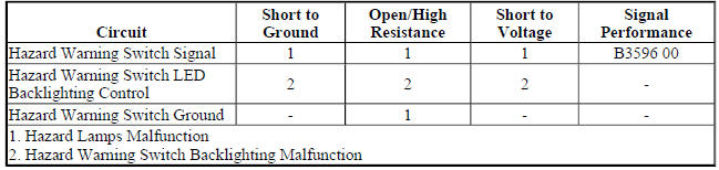
Circuit/System Description
The hazard flashers may be activated in any power mode. The hazard warning switch signal circuit is momentarily grounded when the hazard warning switch is pressed. The body control module (BCM) responds to the hazard warning switch signal input by supplying battery voltage to all four turn signal lamps in an ON and OFF duty cycle. When the hazard warning switch is activated, the BCM sends a serial data message to the instrument cluster requesting both turn signal indicators to be cycled ON and OFF.
The instrument panel dimmer switch controls are located on the headlamp switch assembly and are used to increase and decrease the brightness of the interior backlighting components. When the instrument panel dimmer switch is placed in a desired brightness position, the body control module (BCM) receives a signal from the instrument panel dimmer switch and responds by applying a pulse width modulated (PWM) voltage to the hazard switch LED backlighting control circuit illuminating the LED to the desired level of brightness.
Reference Information
Schematic Reference
Exterior Lights Schematics (Encore) , Exterior Lights Schematics (Trax)
Connector End View Reference
WIRING SYSTEMS AND POWER MANAGEMENT - COMPONENT CONNECTOR END VIEWS - INDEX - ENCORE WIRING SYSTEMS AND POWER MANAGEMENT - COMPONENT CONNECTOR END VIEWS - INDEX - TRAX
Description and Operation
Exterior Lighting Systems Description and Operation
Electrical Information Reference
- Circuit Testing
- Connector Repairs
- Testing for Intermittent Conditions and Poor Connections
- Wiring Repairs
Scan Tool Reference
Control Module References for scan tool information
Circuit/System Verification
- Ignition ON.
- Verify the scan tool Hazard Lamps Switch parameter changes between Active and Inactive while commanding the hazard lamps ON and OFF with the hazard warning switch.
- If the parameter does not change
Refer to Hazard Warning Switch Malfunction
- If the parameter changes
- Verify all left and right turn signal lamps turn ON and OFF while commanding the hazard lamps ON and OFF with the hazard warning switch.
- If all turn signal lamps do not turn ON and OFF
Refer to Turn Signal Lamps and/or Indicators Malfunction
- If all turn signal lamps turn ON and OFF
- Verify the hazard warning switch backlighting turns ON and OFF while commanding the Hazard Lamps Switch Backlight ON and OFF with a scan tool.
- If the hazard warning switch backlighting does not turn ON and OFF
Refer to Hazard Warning Switch Backlighting Malfunction.
- If the hazard warning switch backlighting turns ON and OFF
- All OK.
Circuit/System Testing
Hazard Warning Switch Malfunction
- Ignition OFF, scan tool disconnected, all doors closed, all accessories OFF, disconnect the harness connector at the S26 Hazard Warning Switch. It may take up to 2 minutes for all vehicle systems to power down.
- Test for less than 5 ohms between the ground circuit terminal 7 and ground.
- If 5 ohms or greater
- Ignition OFF.
- Test for less than 2 ohms in the ground circuit end to end.
- If 2 ohms or greater, repair the open/high resistance in the circuit.
- If less than 2 ohms, repair the open/high resistance in the ground connection.
- If less than 5 ohms
- Ignition ON.
- Verify the scan tool Hazard Lamps Switch parameter is Inactive.
- If not Inactive
- Ignition OFF, disconnect the X2 harness connector at the K9 Body Control Module.
- Test for infinite resistance between the signal circuit terminal 10 and ground.
- If less than infinite resistance, repair the short to ground on the circuit.
- If infinite resistance, replace the K9 Body Control Module.
- If Inactive
- Install a 3 A fused jumper wire between the signal circuit terminal 10 and ground.
- Verify the scan tool Hazard Lamps Switch parameter is Active.
- If not Active
- Ignition OFF, disconnect the X2 harness connector at the K9 Body Control Module, ignition ON.
- Test for less than 1 V between the signal circuit terminal 10 and ground.
- If 1 V or greater, repair the short to voltage on the circuit.
- If less than 1 V
- Test for less than 2 ohms in the signal circuit end to end.
- If 2 ohms or greater, repair the open/high resistance in the circuit.
- If less than 2 ohms, replace the K9 Body Control Module.
- If Active
- Test or replace the S26 Hazard Warning Switch.
Hazard Warning Switch Backlighting Malfunction
- Ignition OFF, scan tool disconnected, all doors closed, all accessories OFF, disconnect the harness connector at the S26 Hazard Warning Switch. It may take up to 2 minutes for all vehicle systems to power down.
- Test for less than 5 ohms between the ground circuit terminal 7 and ground.
- If 5 ohms or greater
- Ignition OFF.
- Test for less than 2 ohms in the ground circuit end to end.
- If 2 ohms or greater, repair the open/high resistance in the circuit.
- If less than 2 ohms, repair the open/high resistance in the ground connection.
- If less than 5 ohms
- Connect a test lamp between the control circuit terminal 5 and ground, ignition ON.
- Verify the test lamp turns ON and OFF when commanding the Hazard Lamps Switch Backlight ON and OFF with a scan tool.
- If the test lamp is always OFF
- Ignition OFF, disconnect the X1 harness connector at the K9 Body Control Module.
- Test for infinite resistance between the control circuit and ground.
- If less than infinite resistance, repair the short to ground on the circuit.
- If infinite resistance
- Test for less than 2 ohms in the control circuit end to end.
- If 2 ohms or greater, repair the open/high resistance in the circuit.
- If less than 2 ohms, replace the K9 Body Control Module.
- If the test lamp is always ON
- Ignition OFF, disconnect the X1 harness connector at the K9 Body Control Module, ignition ON.
- Test for less than 1 V between the control circuit terminal and ground.
- If 1 V or greater, repair the short to voltage on the circuit.
- If less than 1 V, replace the K9 Body Control Module.
- If the test lamp turns ON and OFF
- Test or replace the S26 Hazard Warning Switch.
Repair Instructions
Perform the Diagnostic Repair Verification after completing the repair.
- Hazard Warning and Accessory Switch Replacement (Encore)
- Control Module References for BCM replacement, programming, and setup
