Chevrolet Trax: Interior backlighting malfunction
Diagnostic Instructions
- Perform the Diagnostic System Check - Vehicle prior to using this diagnostic procedure.
- Review Strategy Based Diagnosis for an overview of the diagnostic approach.
- Diagnostic Procedure Instructions provides an overview of each diagnostic category
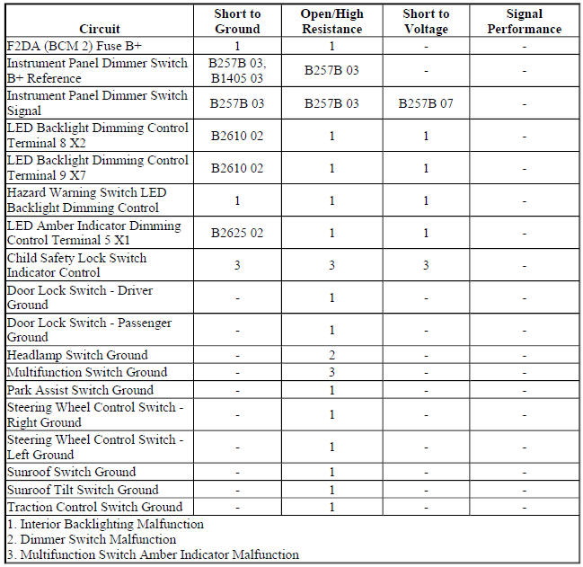
Diagnostic Fault Information
Circuit/System Description
The instrument panel dimmer switch is used to increase and decrease the brightness of the interior backlighting components. The instrument panel dimmer switch provides a voltage signal to the body control module (BCM) that will increase as the brightness of the lights are increased and decrease as the brightness of the lights are decreased. The BCM provides a low reference signal and a B+ voltage reference to the instrument panel dimmer switch. When the instrument panel dimmer switch is placed in the desired position, the dimmed voltage setting is applied from the instrument panel dimmer switch through the instrument panel dimmer switch signal circuit to the BCM. The BCM interprets the signal and applies a pulse width modulated (PWM) voltage through the LED dimming control circuits illuminating the interior backlighting to the requested level of brightness.
Reference Information
Schematic Reference
Interior Lights Dimming Schematics (Encore) , Interior Lights Dimming Schematics (Trax)
Connector End View Reference
WIRING SYSTEMS AND POWER MANAGEMENT - COMPONENT CONNECTOR END VIEWS - INDEX - ENCORE WIRING SYSTEMS AND POWER MANAGEMENT - COMPONENT CONNECTOR END VIEWS - INDEX - TRAX
Description and Operation
Interior Lighting Systems Description and Operation
Electrical Information Reference
- Circuit Testing
- Connector Repairs
- Testing for Intermittent Conditions and Poor Connections Wiring Repairs
Scan Tool Reference
Control Module References for scan tool information
Circuit/System Verification
- Ignition ON.
- Verify the scan tool LED Backlight Dimming Command parameter changes between a high percentage to a low percentage while operating the dimmer switch from high to low.
- If the parameter does not change
Refer to Dimmer Switch Malfunction.
- If the parameter changes
- Verify the child safety lock switch amber LED indicator turns ON and OFF while commanding the Child Safety Lock Indicator ON and OFF with a scan tool.
- If the child safety lock switch amber indicator does turn ON and OFF
Refer to Multifunction Switch Amber Indicator Malfunction.
- If the child safety lock switch amber indicator turns ON and OFF
- Verify all backlighting components turn ON and OFF while commanding the LED Backlight Dimming ON and OFF with a scan tool.
- If all backlighting components do not turn ON and OFF
Refer to Interior Backlighting Malfunction.
- If all backlighting components turn ON and OFF
- All OK.
Circuit/System Testing
Dimmer Switch Malfunction
- Ignition OFF and all vehicle systems OFF, disconnect the harness connector at the S30 Headlamp Switch, ignition ON.
- Test for B+ between the B+ circuit terminal 1 and ground.
- If less than B+
- Ignition OFF, disconnect the X3 harness connector at the K9 Body Control Module.
- Test for infinite resistance between the B+ circuit and ground.
- If less than infinite resistance, repair the short to ground on the circuit.
- If infinite resistance
- Test for less than 2 ohms in the B+ circuit end to end.
- If 2 ohms or greater, repair the open/high resistance in the circuit.
- If less than 2 ohms, replace the K9 Body Control Module.
- If B+
- Verify a test lamp does not illuminate between the B+ circuit terminal 1 and the signal circuit terminal 12.
- If the test lamp illuminates
- Ignition OFF, disconnect the X1 harness connector at the K9 Body Control Module.
- Test for infinite resistance between the signal circuit and ground.
- If less than infinite resistance, repair the short to ground on the circuit.
- If infinite resistance, replace the K9 Body Control Module.
- If the test lamp does not illuminate
- Test for B+ between the B+ circuit terminal 1 and the signal circuit terminal 12.
- If less than B+
- Ignition OFF, disconnect the X1 harness connector at the K9 Body Control Module, ignition ON.
- Test for less than 1 V between the signal circuit terminal 12 and ground.
- If 1 V or greater, repair the short to voltage on the circuit.
- If less than 1 V
- Test for less than 2 ohms in the signal circuit end to end.
- If 2 ohms or greater, repair the open/high resistance in the circuit.
- If less than 2 ohms, replace the K9 Body Control Module.
- If B+
- Test or replace the S30 Headlamp Switch.
Multifunction Switch Amber Indicator Malfunction
- Ignition OFF, disconnect the appropriate harness connector listed below at the S48E Multifunction Switch - Center Console.
- X1
- X2
- Connect a test lamp between the control circuit terminal 8 and ground, ignition ON.
- Verify the test lamp turns ON and OFF when commanding the Child Safety Lock Indicator ON and OFF with a scan tool.
- If the test lamp is always OFF
- Ignition OFF, disconnect the X1 harness connector at the K9 Body Control Module.
- Test for infinite resistance between the control circuit and ground.
- If less than infinite resistance, repair the short to ground on the circuit.
- If infinite resistance
- Test for less than 2 ohms in the control circuit end to end.
- If 2 ohms or greater, repair the open/high resistance in the circuit.
- If less than 2 ohms, replace the K9 Body Control Module.
- If the test lamp is always ON
- Ignition OFF, disconnect the X1 harness connector at the K9 Body Control Module, ignition ON.
- Test for less than 1 V between the control circuit terminal and ground.
- If 1 V or greater, repair the short to voltage on the circuit.
- If less than 1 V, replace the K9 Body Control Module.
- If the test lamp turns ON and OFF
- Test or replace the appropriate switch at the S48E Multifunction Switch - Center Console.
Interior Backlighting Malfunction
NOTE: Each component with backlighting may need to be disconnected to isolate a short to voltage or short to ground. Use the schematics to identify the following:
- Backlighting components the vehicle is equipped with
- Each component's control and ground circuit terminals
- Component locations on the backlighting control circuit
- Ignition OFF, disconnect the X1 harness connector at the K9 Body Control Module, ignition ON.
- Verify a test lamp illuminates between the B+ circuit terminal 4 and ground.
- If the test lamp does not illuminate and the circuit fuse is good
- Ignition OFF.
- Test for less than 2 ohms in the B+ circuit end to end.
- If 2 ohms or greater, repair the open/high resistance in the circuit.
- If less than 2 ohms, verify the fuse is not open and there is voltage at the fuse.
- If the test lamp does not illuminate and the circuit fuse is open
- Ignition OFF.
- Test for infinite resistance between the B+ circuit and ground.
- If less than infinite resistance, repair the short to ground on the circuit.
- If infinite resistance, replace the K9 Body Control Module.
- If the test lamp illuminates
- Ignition OFF, connect the X1 harness connector at the K9 Body Control Module.
- Ignition OFF, all doors closed, all accessories OFF, disconnect the harness connector at the component with inoperative backlighting. It may take up to 2 minutes for all vehicle systems to power down.
- Test for less than 15 ohms between the appropriate ground circuit terminal and ground.
- If 15 ohms or greater
- Ignition OFF.
- Test for less than 2 ohms in the ground circuit end to end.
- If 2 ohms or greater, repair the open/high resistance in the circuit.
- If less than 2 ohms, repair the open/high resistance in the ground connection.
- If less than 15 ohms
- Connect a test lamp between the appropriate control circuit terminal and ground.
- Verify the test lamp turns ON and OFF when commanding the LED Backlight Dimming ON and OFF with a scan tool.
- If the test lamp is always OFF
- Ignition OFF, disconnect the appropriate harness connector at the K9 Body Control Module.
- Test for infinite resistance between the control circuit and ground.
- If less than infinite resistance, repair the short to ground on the circuit.
- If infinite resistance
- Test for less than 2 ohms in the control circuit end to end.
- If 2 ohms or greater, repair the open/high resistance in the circuit.
- If less than 2 ohms, replace the K9 Body Control Module.
- If the test lamp is always ON
- Ignition OFF, disconnect the appropriate harness connector at the K9 Body Control Module, ignition ON.
- Test for less than 1 V between the control circuit terminal and ground.
- If 1 V or greater, repair the short to voltage on the circuit.
- If less than 1 V, replace the K9 Body Control Module.
- If the test lamp turns ON and OFF
- Test or replace the component with inoperative backlighting.
Hazard Warning Switch Backlighting Malfunction
- Ignition OFF, scan tool disconnected, all doors closed, all accessories OFF, disconnect the harness connector at the S26 Hazard Warning Switch. It may take up to 2 minutes for all vehicle systems to power down.
- Test for less than 5 ohms between the ground circuit terminal 7 and ground.
- If 5 ohms or greater
- Ignition OFF.
- Test for less than 2 ohms in the ground circuit end to end.
- If 2 ohms or greater, repair the open/high resistance in the circuit.
- If less than 2 ohms, repair the open/high resistance in the ground connection.
- If less than 5 ohms
- Connect a test lamp between the control circuit terminal 5 and ground, ignition ON.
- Verify the test lamp turns ON and OFF when commanding the Hazard Lamps Switch Backlight ON and OFF with a scan tool.
- If the test lamp is always OFF
- Ignition OFF, disconnect the X1 harness connector at the K9 Body Control Module.
- Test for infinite resistance between the control circuit and ground.
- If less than infinite resistance, repair the short to ground on the circuit.
- If infinite resistance
- Test for less than 2 ohms in the control circuit end to end.
- If 2 ohms or greater, repair the open/high resistance in the circuit.
- If less than 2 ohms, replace the K9 Body Control Module.
- If the test lamp is always ON
- Ignition OFF, disconnect the X1 harness connector at the K9 Body Control Module, ignition ON.
- Test for less than 1 V between the control circuit terminal and ground.
- If 1 V or greater, repair the short to voltage on the circuit.
- If less than 1 V, replace the K9 Body Control Module.
- If the test lamp turns ON and OFF
- Test or replace the S26 Hazard Warning Switch.
Repair Instructions
Perform the Diagnostic Repair Verification after completing the repair.
- Rear Side Door Window Switch Replacement
- Instrument Panel Multifunction Switch Replacement (Encore)
- Hazard Warning and Accessory Switch Replacement (Encore)
- Headlamp Switch Replacement (Encore) , Headlamp Switch Replacement (Trax)
- Door Lock Switch Replacement - Driver Side (Encore) , Door Lock Switch Replacement - Driver Side (Trax)
- Door Lock Switch Replacement - Passenger Front (Encore) , Door Lock Switch Replacement - Passenger Front (Trax)
- Transmission Control Replacement
- Outside Rearview Mirror Remote Control Switch Replacement (Encore) , Outside Rearview Mirror Remote Control Switch Replacement (Trax)
- Radio and Telephone Control Switch Replacement
- Control Module References for BCM replacement, programming, and setup
