Chevrolet Trax: DTC U0400-U05FF: See control module U code list
Diagnostic Instructions
- Perform the Diagnostic System Check - Vehicle prior to using this diagnostic procedure.
- Review Strategy Based Diagnosis for an overview of the diagnostic approach.
- Diagnostic Procedure Instructions provides an overview of each diagnostic category.
DTC Descriptor
Refer to Control Module U Code List.
Circuit/System Description
Some devices are constantly receiving information from other devices through serial data communication network. The invalid data code will be set when a receiving device detects a discrepancy in information it receives from another device causing its integrity to be questioned. The symptom byte listed in the DTC Descriptor is for engineering reference only. No external circuit diagnosis is involved.
Conditions for Running the DTC
Battery voltage is between 9-16 V and data link communications operate normally.
Conditions for Setting the DTC
The device is not configured properly.
Conditions for Clearing the DTC
- A current DTC clears when the malfunction is no longer present.
- A history DTC clears when the device ignition cycle counter reaches the reset threshold, without a repeat of the malfunction.
Reference Information
Schematic Reference
- Data Communication Schematics (Encore), Data Communication Schematics (Trax)
- Control Module References
Connector End View Reference
WIRING SYSTEMS AND POWER MANAGEMENT - COMPONENT CONNECTOR END VIEWS - INDEX - ENCORE WIRING SYSTEMS AND POWER MANAGEMENT - COMPONENT CONNECTOR END VIEWS - INDEX - TRAX
Description and Operation
Data Link Communications Description and Operation
Electrical Information Reference
- Circuit Testing
- Connector Repairs
- Testing for Intermittent Conditions and Poor Connections
- Wiring Repairs
Scan Tool Reference
Control Module References for scan tool information
Circuit/System Verification
- Engine running for 10 s.
- Ignition ON, engine OFF, verify DTC U0400-U05FF is not set.
If DTC U0400-U05FF is set along with other DTCs set
Diagnose all other DTCs first. Refer to Diagnostic Trouble Code (DTC) List - Vehicle .
If DTC U0400-U05FF is set without other DTCs set
- Program the device specified by the DTC descriptor.
- Verify the DTC does not set.
- If the DTC sets, replace the appropriate device.
- If the DTC does not set
- All OK.
Repair Instructions
Perform the Diagnostic Repair Verification after completing the repair.
Control Module References for device replacement, programming and setup
DTC U1500-U15FF: SEE CONTROL MODULE U CODE LIST
Diagnostic Instructions
- Perform the Diagnostic System Check - Vehicle prior to using this diagnostic procedure.
- Review Strategy Based Diagnosis for an overview of the diagnostic approach.
- Diagnostic Procedure Instructions provides an overview of each diagnostic category.
DTC Descriptor
For device DTC descriptors, refer to Control Module U Code List.
Diagnostic Fault Information
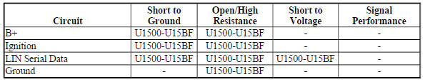
Circuit/System Description
The serial data is transmitted over a Local Interconnect Network (LIN) single wire network circuit bus between a master control module and other LIN devices within a particular subsystem. If serial data communication is lost between any of the LIN devices on the LIN bus network, a no communication code against the noncommunicating LIN device will be set. A master control module is the one that reports the non communication code.
Conditions for Running the DTC
The system voltage is between 9-16 V.
Conditions for Setting the DTC
A supervised periodic message that includes the transmitter device availability has not been received.
Action Taken When the DTC Sets
Specific subsystems will not function.
Conditions for Clearing the DTC
- A current DTC clears when the malfunction is no longer present.
- A history DTC clears when the device ignition cycle counter reaches the reset threshold of 50, without a repeat of the malfunction.
Diagnostic Aids
Sometimes, while diagnosing a specific customer concern or after a repair, you may notice a history U code present. However, there is no associated "current" or "active" status. Loss of communication U codes such as these can set for a variety of reasons. Many times, they are transparent to the vehicle operator and technician, and/or have no associated symptoms. Eventually, they will erase themselves automatically after a number of fault-free ignition cycles. This condition would most likely be attributed to one of these scenarios:
- A device on the data communication circuit was disconnected while the communication circuit is awake.
- Power to one or more devices was interrupted during diagnosis.
- A low battery condition was present, so some devices stop communicating when battery voltage drops below a certain threshold.
- Battery power was restored to the vehicle and devices on the communication circuit did not all reinitialize at the same time.
- If a loss of communication U code appears in history for no apparent reason, it is most likely associated with one of the scenarios above. These are all temporary conditions and should never be interpreted as an intermittent fault, causing you to replace a part.
- A device may have a U code stored in history that does not require any repairs. Issues with late or corrupted messages between devices can be temporary with no apparent symptom or complaint; this does not mean the device is faulty. Do not replace a device based only on a history U code.
- Do not replace a device reporting a U code. The U code identifies which device needs to be diagnosed for a communication issue.
- Communication will be available between the master control module and the scan tool if there is a loss of communications with any of the other LIN devices on the LIN bus network.
- Some devices may not have internal protection for specific control circuits and may open a B+ or ignition fuse. If a fuse is open and the B+ or ignition circuit is not shorted to ground, ensure none of the control circuits are shorted to ground before replacing the device.
- Some intermittent communication concerns may be caused by fretting corrosion on the serial data circuit terminals. Inspect all connectors at the device that set the communication DTC, the device that the communication DTC was set against, and any inline harness connectors between the two devices. Do not replace a device based only on fretting corrosion. Refer to bulletin 09-06-03-004 for assistance with the diagnosis and repair of this condition, if applicable.
- An open in the LIN bus serial data circuit between the splice pack and a LIN device will only affect that specific LIN device. This type of failure will set a loss of communication DTC for each LIN device affected and the other LIN devices will still communicate.
Reference Information
Schematic Reference
- Data Communication Schematics (Encore), Data Communication Schematics (Trax)
- Control Module References
Connector End View Reference
WIRING SYSTEMS AND POWER MANAGEMENT - COMPONENT CONNECTOR END VIEWS - INDEX - ENCORE WIRING SYSTEMS AND POWER MANAGEMENT - COMPONENT CONNECTOR END VIEWS - INDEX - TRAX
Description and Operation
Data Link Communications Description and Operation
Electrical Information Reference
- Circuit Testing
- Connector Repairs
- Testing for Intermittent Conditions and Poor Connections
- Wiring Repairs
Scan Tool Reference
Control Module References for scan tool information
Circuit/System Verification
- Determine the LIN device that is not communicating. Refer to Control Module U Code List.
- Verify that DTC B1325, B1330, B1370, B1380, B1424, B1440, B1441, B1517, C0800, C0899, C12E1, P0560, or P0562 is not set.
If any of the DTCs are set
Refer to Diagnostic Trouble Code (DTC) List - Vehicle .
If none of the DTCs are set
- Verify that DTC U0100-U02FF is not set.
If any of the DTCs are set
Refer to DTC U0100-U02FF.
If none of the DTCs are set
- Refer to Circuit/System Testing.
Circuit/System Testing
NOTE:
- For some vehicles, both headlamps may be connected to the same LIN circuit through a splice. Or both LIN circuits to the headlamps may be internally connected at the connector of the K26 Headlamp Control Module or K28 Headlamp Leveling Control Module. A short in one headlamp or its LIN circuit may cause no communication to both headlamps. Ensure to diagnose both LIN circuits and headlamps prior to replacing a headlamp.
- Use the schematic to identify the following:
- The master control module and the LIN devices on the same LIN serial data circuit
- The master control module's LIN serial data circuit terminal and the LIN device's B+, ignition, ground, and LIN serial data circuit terminals
- Ignition OFF, all access doors closed, all vehicle systems OFF, and all keys at least 3 m (9.8 ft) away from vehicle. Disconnect the harness connector at a LIN device that is not communicating. It may take up to 2 min for all vehicle systems to power down.
- Test for less than 10 ohms between each ground circuit terminal and ground.
If 10 ohms or greater
- Ignition OFF.
- Test for less than 2 ohms in the ground circuit end to end.
- If 2 ohms or greater, repair the open/high resistance in the circuit.
- If less than 2 ohms, repair the open/high resistance in the ground connection.
If less than 10 ohms
- Ignition ON.
- Verify a test lamp illuminates between each B+ circuit terminal and ground, if equipped.
If the test lamp does not illuminate and the circuit fuse is good
- Ignition OFF.
- Test for less than 2 ohms in the B+ circuit end to end.
- If 2 ohms or greater, repair the open/high resistance in the circuit.
- If less than 2 ohms, verify the fuse is not open and there is voltage at the fuse
If the test lamp does not illuminate and the circuit fuse is open
- Ignition OFF.
- Test for infinite resistance between the B+ circuit and ground.
- If less than infinite resistance, repair the short to ground on the circuit.
- If infinite resistance, replace the disconnected LIN device.
If the test lamp illuminates
- Ignition ON.
- Verify a test lamp illuminates between each ignition circuit terminal and ground, if equipped.
If the test lamp does not illuminate and the circuit fuse is good
- Ignition OFF.
- Test for less than 2 ohms in the ignition circuit end to end.
- If 2 ohms or greater, repair the open/high resistance in the circuit.
- If less than 2 ohms, verify the fuse is OK and there is voltage at the fuse.
If the test lamp does not illuminate and the circuit fuse is open
- Ignition OFF.
- Test for infinite resistance between the ignition circuit and ground.
- If less than infinite resistance, repair the short to ground on the circuit.
- If infinite resistance, replace the disconnected LIN device.
If the test lamp illuminates
- Ignition ON.
- Verify a test lamp illuminates between each ignition circuit terminal, which is controlled by a control module, and ground, if equipped.
If the test lamp does not illuminate
- Ignition OFF, disconnect the harness connectors at the control module that controls the ignition circuit.
- Test for infinite resistance between the ignition circuit and ground.
- If less than infinite resistance, repair the short to ground on the circuit.
- If infinite resistance
- Test for less than 2 ohms in the ignition circuit end to end.
- If 2 ohms or greater, repair the open/high resistance in the circuit.
- If less than 2 ohms, replace the control module that controls the ignition circuit
- If the test lamp illuminates
- Ignition ON.
NOTE: For accurate voltage reading, disconnect the battery charger prior to performing the following test step.
- Test for 2-13 V between the LIN serial data circuit terminal and ground.
If less than 2 V
- Ignition OFF, disconnect the harness connector at the control module setting the DTC and all LIN devices that share the same LIN serial data circuit.
- Test for infinite resistance between the serial data circuit and ground.
- If less than infinite resistance, repair the short to ground on the circuit.
- If infinite resistance
- Test for less than 2 ohms in the serial data circuit end to end.
- If 2 ohms or greater, repair the open/high resistance in the circuit.
- If less than 2 ohms
- Reconnect the control module that set the DTC, ignition ON.
- Test for 2-13 V between the LIN serial data circuit terminal and ground.
- If less than 2 V, replace the control module setting the DTC.
- If greater than 2 V, replace the LIN device that causes a current DTC to set when connected
If greater than 13 V
- Ignition OFF, disconnect the harness connector at the control module setting the DTC and all LIN devices that share the same LIN serial data circuit.
- Ignition ON.
- Test for less than 1 V between the serial data circuit and ground.
- If 1 V or greater, repair the short to voltage on the circuit.
- If less than 1 V
- Ignition OFF, reconnect the control module that set the DTC, ignition ON.
- Test for 2-13 V between the LIN serial data circuit terminal and ground.
- If greater than 13 V, replace the control module setting the DTC.
- If less than 13 V, replace the LIN device that causes a current DTC to set when connected.
If between 2-13 V
- Replace the disconnected LIN device.
Repair Instructions
Perform the Diagnostic Repair Verification after completing the repair.
- GMLAN and Media Oriented Systems Transport (MOST) Wiring Repairs
- Control Module References for device replacement, programming and setup
READ NEXT:
 DTC U1814: Powertrain wake-up communication circuit
Diagnostic Instructions
Perform the Diagnostic System Check - Vehicle prior to using this
diagnostic procedure.
Review Strategy Based Diagnosis for an overview of the diagnostic
approach.
Diag
DTC U18A6: Lost communication with right object detection control module on
dedicated bus 1
Diagnostic Instructions
Perform the Diagnostic System Check - Vehicle prior to using this
diagnostic procedure.
Review Strategy Based Diagnosis for an overview of the diagnostic
approach.
Diag
DTC U18B9-U18BF: High speed can bus subnet configuration list
Diagnostic Instructions
Perform the Diagnostic System Check - Vehicle prior to using this
diagnostic procedure.
Review Strategy Based Diagnosis for an overview of the diagnostic
approach.
Diag
SEE MORE:
DTC U0074: Control module communication bus B OFF
Diagnostic Instructions
Perform the Diagnostic System Check - Vehicle prior to using this
diagnostic procedure.
Review Strategy Based Diagnosis for an overview of the diagnostic
approach.
Diagnostic Procedure Instructions provides an overview of each
diagnostic category.
DTC Descriptor
DT
Front brake shield replacement
Removal Procedure
WARNING: Refer to Brake Dust Warning .
Raise and support the vehicle. Refer to Lifting and Jacking the Vehicle
.
Remove the front tire and wheel assembly. Refer to Tire and Wheel
Removal and Installation .
Remove the front brake rotor. Refer to Front Brake Rotor Replacement
