Chevrolet Trax: DTC U18A6: Lost communication with right object detection control module on dedicated bus 1
Diagnostic Instructions
- Perform the Diagnostic System Check - Vehicle prior to using this diagnostic procedure.
- Review Strategy Based Diagnosis for an overview of the diagnostic approach.
- Diagnostic Procedure Instructions provides an overview of each diagnostic category.
DTC Descriptor
DTC U18A6
Lost Communication with Right Object Detection Control Module on Dedicated Bus 1
For symptom byte information, refer to Symptom Byte List .
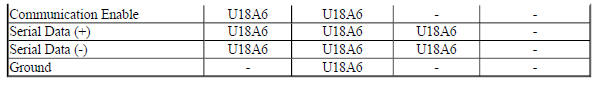
Diagnostic Fault Information
.jpg)
Circuit/System Description
The side object sensor modules use radar to determine the presence of objects nearby. The left side object sensor is the master that communicates on serial data. There is a private communication network between the left and right sensors. The scan tool can communicate only with the left sensor. Side blind zone alert is active when the vehicle is out of park or the parking brake is off on manual transmission vehicles. If a vehicle is detected in the side blind zone, the warning symbols will illuminate on the appropriate side. The warning symbols will vary brightness based on the ambient light conditions. When an object is detected in the left side blind zone, the side object sensor module sends a message to the right sensor through serial data. The right sensor then supplies voltage to illuminate the visual indicator on the left side outside rear view mirror. When an object is detected in the right side blind zone, the right side object sensor will supply a voltage to illuminate the visual indicator on the right side outside rear view mirror.
Conditions for Running the DTC
The system voltage is between 9-16 V.
Conditions for Setting the DTC
A supervised periodic message that includes the transmitter device availability has not been received.
Action Taken When the DTC Sets
Specific subsystems will not function.
Conditions for Clearing the DTC
- A current DTC clears when the malfunction is no longer present.
- A history DTC clears when the device ignition cycle counter reaches the reset threshold of 40, without a repeat of the malfunction.
Reference Information
Schematic Reference
- Object Detection Schematics (Encore) , Object Detection Schematics (Trax)
- Data Communication Schematics (Encore), Data Communication Schematics (Trax)
- Control Module References
Connector End View Reference
WIRING SYSTEMS AND POWER MANAGEMENT - COMPONENT CONNECTOR END VIEWS - INDEX - ENCORE WIRING SYSTEMS AND POWER MANAGEMENT - COMPONENT CONNECTOR END VIEWS - INDEX - TRAX
Description and Operation
- Object Detection Description and Operation (Rearvision Camera, UVC) , Object Detection Description and Operation (Rear Park Assist, UD7) , Object Detection Description and Operation (Side Blind Zone Alert, UFT) , Object Detection Description and Operation (Rear Cross Traffic Alert, UFG)
- Data Link Communications Description and Operation
Electrical Information Reference
- Circuit Testing
- Connector Repairs
- Testing for Intermittent Conditions and Poor Connections
- Wiring Repairs
Scan Tool Reference
Control Module References for scan tool information
Circuit/System Verification
- Verify that DTC U0073, U0078, B1325, B1330, B1370, B1380, B1424, B1440, B1441, B1517, C0800, C0899, C12E1, P0560, or P0562 is not set.
If any of the DTCs are set
Refer to Diagnostic Trouble Code (DTC) List - Vehicle .
If none of the DTCs are set
- Refer to Circuit/System Testing.
Circuit/System Testing
NOTE: Use the schematics and connector end views to identify the device's ground, B+, and serial data circuit terminals.
- Ignition OFF, all access doors closed, all vehicle systems OFF, and all keys at least 3 m (9.8 ft) away from vehicle. It may take up to 2 min for all vehicle systems to power down. Disconnect the harness connector at the B218R Side Object Sensor Module - Right.
- Test for less than 10 ohms between each ground circuit terminal and ground.
If 10 ohms or greater
- Ignition OFF.
- Test for less than 2 ohms in the ground circuit end to end.
- If 2 ohms or greater, repair the open/high resistance in the circuit.
- If less than 2 ohms, repair the open/high resistance in the ground connection.
If less than 10 ohms
- Ignition ON.
- If equipped, verify a test lamp illuminates between each B+ circuit terminal and ground.
If the test lamp does not illuminate and the circuit fuse is good
- Ignition OFF.
- Test for less than 2 ohms in the B+ circuit end to end.
- If 2 ohms or greater, repair the open/high resistance in the circuit.
- If less than 2 ohms, verify the fuse is not open and there is voltage at the fuse.
If the test lamp does not illuminate and the circuit fuse is open
- Ignition OFF.
- Test for infinite resistance between the B+ circuit and ground.
- If less than infinite resistance, repair the short to ground on the circuit.
- If infinite resistance, replace the B218R Side Object Sensor Module - Right.
If the test lamp illuminates
- Ignition ON.
- If equipped, test for at least 6 V between the communication enable circuit terminal and ground.
If less than 6 V
- Ignition OFF, disconnect the harness connectors at the B218L Side Object Sensor Module - Left.
- Test for infinite resistance between the communication enable circuit terminal and ground.
- If less than infinite resistance, repair the short to ground on the circuit.
- If infinite resistance
- Test for less than 2 ohms in the communication enable circuit end to end.
- If 2 ohms or greater, repair the open/high resistance in the circuit.
- If less than 2 ohms, replace the B218L Side Object Sensor Module - Left.
If 6 V or greater
- Ignition OFF, all access doors closed, all vehicle systems OFF, and all keys at least 3 m (9.8 ft) away from vehicle. It may take up to 2 min for all vehicle systems to power down. Disconnect the harness connector at the B218L Side Object Sensor Module - Left.
- Test for less than 1 V between each serial data circuits and ground.
If 1 V or greater
Repair the short to voltage in the serial data circuit.
If less than 1 V
- Test for infinite resistance between each serial data circuits and ground.
If less than infinite resistance
Repair the short to ground in the serial data circuit.
If infinite resistance
- Test for infinite resistance between 2 serial data circuits.
If less than infinite resistance
Repair the short together between the serial data circuits.
If infinite resistance
- Test for less than 2 ohms in each of the serial data circuits end to end between the B218L Side Object Sensor Module - Left and the B218R Side Object Sensor Module - Right.
If 2 ohms or greater
Repair the open/high resistance in the serial data circuit.
If less than 2 ohms
- Replace the B218R Side Object Sensor Module - Right.
Repair Instructions
Perform the Diagnostic Repair Verification after completing the repair.
- GMLAN and Media Oriented Systems Transport (MOST) Wiring Repairs
- Control Module References for device replacement, programming and setup
READ NEXT:
 DTC U18B9-U18BF: High speed can bus subnet configuration list
Diagnostic Instructions
Perform the Diagnostic System Check - Vehicle prior to using this
diagnostic procedure.
Review Strategy Based Diagnosis for an overview of the diagnostic
approach.
Diag
DTC U2099: High speed communication enable circuit
Diagnostic Instructions
Perform the Diagnostic System Check - Vehicle prior to using this
diagnostic procedure.
Review Strategy Based Diagnosis for an overview of the diagnostic
approach.
Diag
Symptoms - data communications
NOTE: The following steps must be completed before using the
symptom tables.
Perform the Diagnostic System Check - Vehicle before using the symptom
tables in order to verify that
all of the foll
SEE MORE:
Vehicle Data Recording and
Privacy
The vehicle has a number of
computers that record information
about the vehicle's performance and
how it is driven. For example, the
vehicle uses computer modules to
monitor and control engine and
transmission performance, to
monitor the conditions for airbag
deployment and deploy them in a
crash, a
DTC B2470: Cellular phone antenna
Diagnostic Instructions
Perform the Diagnostic System Check - Vehicle prior to using this
diagnostic procedure.
Review Strategy Based Diagnosis for an overview of the diagnostic
approach.
Diagnostic Procedure Instructions provides an overview of each
diagnostic category
DTC Descriptors
DT
