Chevrolet Trax: DTC U0074: Control module communication bus B OFF
Diagnostic Instructions
- Perform the Diagnostic System Check - Vehicle prior to using this diagnostic procedure.
- Review Strategy Based Diagnosis for an overview of the diagnostic approach.
- Diagnostic Procedure Instructions provides an overview of each diagnostic category.
DTC Descriptor
DTC U0074
Control Module Communication Bus B Off
For symptom byte information, refer to Symptom Byte List .
Diagnostic Fault Information
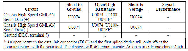
.jpg)
Circuit/System Description
The devices connected to the chassis high speed GMLAN serial data circuits monitor for serial data communications during normal vehicle operation. Operating information and commands are exchanged among the devices when the ignition switch is in any position other than OFF. The chassis high speed GMLAN serial data bus uses terminating resistors that are in parallel with the chassis high speed GMLAN (+) and (-) circuits.
Conditions for Running the DTC
The system voltage is between 9-16 V.
Conditions for Setting the DTC
A supervised periodic message that includes the transmitter device availability has not been received.
Action Taken When the DTC Sets
Specific subsystems will not function.
Conditions for Clearing the DTC
- A current DTC clears when the malfunction is no longer present.
- A history DTC clears when the device ignition cycle counter reaches the reset threshold of 50, without a repeat of the malfunction.
Diagnostic Aids
- Use the Data Link References to identify the chassis high speed GMLAN devices.
- Sometimes, while diagnosing a specific customer concern or after a repair, you may notice a history Ucode present. However, there is no associated "current" or "active" status. Loss-of-communication Ucodes such as these can set for a variety of reasons. Many times, they are transparent to the vehicle operator and technician, and/or have no associated symptoms. Eventually, they will erase themselves automatically after a number of fault-free ignition cycles. This condition would most likely be attributed to one of these scenarios:
- A device on the data communication circuit was disconnected while the communication circuit is awake.
- Power to one or more devices was interrupted during diagnosis.
- A low battery condition was present, so some devices stop communicating when battery voltage drops below a certain threshold.
- Battery power was restored to the vehicle and devices on the communication circuit did not all reinitialize at the same time.
- If a loss-of-communication U code appears in history for no apparent reason, it is most likely associated with one of the scenarios above. These are all temporary conditions and should never be interpreted as an intermittent fault, causing you to replace a part.
- Do not replace a device reporting a U code. The U code identifies which device needs to be diagnosed for a communication issue.
- Communication may be available between some devices and the scan tool with the chassis high speed GMLAN serial data system inoperative. This condition is due to those devices using multiple serial data communication systems.
- An open in the DLC ground circuit terminal 5 will allow the scan tool to operate but not communicate with the vehicle.
- Technicians may find various Local Area Network (LAN) communication Diagnostic Trouble Codes (DTC).
- Some devices may not have internal protection for specific voltage outputs and may open a battery positive voltage or ignition voltage source fuse. If a voltage input fuse is open and no short is found in that circuit, ensure that no device output voltage circuit is shorted to ground before replacing the device.
Reference Information
Schematic Reference
- Data Communication Schematics (Encore), Data Communication Schematics (Trax)
- Control Module References
Connector End View Reference
WIRING SYSTEMS AND POWER MANAGEMENT - COMPONENT CONNECTOR END VIEWS - INDEX - ENCORE WIRING SYSTEMS AND POWER MANAGEMENT - COMPONENT CONNECTOR END VIEWS - INDEX - TRAX
Description and Operation
Data Link Communications Description and Operation
Electrical Information Reference
- Circuit Testing
- Connector Repairs
- Testing for Intermittent Conditions and Poor Connections
- Wiring Repairs
Scan Tool Reference
Control Module References for scan tool information
Circuit/System Verification
- Ignition ON.
- Verify two or more devices are not communicating on the chassis high
speed GMLAN serial data circuit.
Refer to Data Link References to determine how many devices should be communicating on the bus.
If only one device is not communicating
Refer to Circuit/System Testing - Testing the Device Circuits.
If two or more devices are not communicating
- Ignition OFF, all access doors closed, all vehicle systems OFF, and all keys at least 3 m (9.8 ft) away from vehicle. Disconnect the scan tool from the X84 Data Link Connector. The following tests will be done at the X84 Data Link Connector. It may take up to 2 minutes for all vehicle systems to power down.
- Test for less than 10 ohms between the ground circuit terminal 5 and ground.
- If 10 ohms or greater
- Ignition OFF.
- Test for less than 2 ohms in the ground circuit end to end.
- If 2 ohms or greater, repair the open/high resistance in the circuit.
- If less than 2 ohms, repair the open/high resistance in the ground connection.
If less than 10 ohms
- Ignition ON.
- Test for less than 4.5 V between the serial data circuits listed below and ground:
- Chassis high speed GMLAN serial data terminal 12
- Chassis high speed GMLAN serial data terminal 13
If 4.5 V or greater
Refer to Circuit/System Testing - Testing the Serial Data Circuits for a Short to Voltage.
If less than 4.5 V
- Ignition OFF, all access doors closed, all vehicle systems OFF, and all keys at least 3 m (9.8 ft) away from vehicle. It may take up to 2 minutes for all vehicle systems to power down.
- Test for greater than 100 ohms between the serial data circuits listed below and ground:
- Chassis high speed GMLAN serial data terminal 12
- Chassis high speed GMLAN serial data terminal 13
If 100 ohms or less
Refer to Circuit/System Testing - Testing the Serial Data Circuits for a Short to Ground.
If greater than 100 ohms
- Test for 50-70 ohms between the serial data circuit terminals 12 and 13:
If less than 35 ohms
Refer to Circuit/System Testing - Testing the Serial Data Circuits for a Short between the Circuits.
If between 35-50 ohms
There may be a third terminating resistor between the serial data circuits. This can happen if the incorrect device is installed. Some devices are available with and without the terminating resistors installed to reduce the need of terminating resistors in the wiring harness. Refer to Circuit/System Testing - Testing the Serial Data Circuits for a Short between the Circuits.
If greater than 70 ohms but less than infinite
Refer to Circuit/System Testing - Testing the Serial Data Circuits for an Open/High Resistance.
If infinite resistance
Repair the open/high resistance in the circuit between the X84 Data Link Connector and the first splice/device in the serial data circuit.
If between 50-70 ohms
- Refer to Circuit/System Testing - Testing the Device Circuits.
Circuit/System Testing
NOTE: Each device may need to be disconnected to isolate a circuit fault.
Use the schematic to identify the following:
- Chassis high speed GMLAN devices the vehicle is equipped with
- Chassis high speed GMLAN serial data circuit terminating resistors
- Device locations on the chassis high speed GMLAN serial data circuits
- Each device's ground, B+, ignition, and chassis high speed GMLAN serial data circuit terminals
Some devices with an internal terminating resistor have a loop in the harness that connects the internal terminating resistor to the serial data circuit. When wired this way, test these loop circuits for the appropriate failure mode short to voltage, short to ground, or open/high resistance prior to replacing the device for each of the following tests.
Testing the Serial Data Circuits for a Short to Voltage
- Ignition OFF, disconnect the harness connectors with the chassis high speed GMLAN serial data circuits at an easily accessible device, ignition ON.
- Test for greater than 4.5 V between each serial data circuit at the device connector that was just disconnected and ground.
If each serial data circuit is 4.5 V or less
- Ignition OFF.
- Test for less than 10 ohms between each of the device's ground circuit terminals and ground.
- If 10 ohms or greater, repair the open/high resistance in the circuit.
- If less than 10 ohms, replace the device that was disconnected.
If any serial data circuit is greater than 4.5 V
- Ignition OFF, disconnect the harness connectors with the chassis high speed GMLAN serial data circuits at another device, in the direction of the circuit shorted to voltage, ignition ON.
- Test for greater than 4.5 V between each serial data circuit at the device connector that was just disconnected and ground.
If each serial data circuit is 4.5 V or less
- Ignition OFF.
- Test for less than 10 ohms between each of the device's ground circuit terminals and ground.
- If 10 ohms or greater, repair the open/high resistance in the circuit.
- If less than 10 ohms, replace the device that was disconnected.
If any serial data circuit is greater than 4.5 V
- Repeat step 3 until one of the following conditions are isolated:
- A short to voltage on the serial data circuit between two devices or splice packs, if equipped.
- A short to voltage on the serial data circuit between a device and a terminating resistor.
Testing the Serial Data Circuits for a Short to Ground
- Ignition OFF, all access doors closed, all vehicle systems OFF, and all keys at least 3 m (9.8 ft) away from vehicle. It may take up to 2 minutes for all vehicle systems to power down.
- Disconnect the harness connectors with the chassis high speed GMLAN serial data circuits at an easily accessible device.
- Test for greater than 100 ohms between each serial data circuit at the device connector that was just disconnected and ground.
If each serial data circuit is 100 ohms or greater
Replace the device that was disconnected.
If any serial data circuit is less than 100 ohms
- Disconnect the harness connectors with the chassis high speed GMLAN serial data circuits at another device, in the direction of the circuit shorted to ground.
- Test for greater than 100 ohms between each serial data circuit at the device connector that was just disconnected and ground.
If both serial data circuits are 100 ohms or greater
Replace the device that was disconnected.
If any serial data circuit is less than 100 ohms
- Repeat step 4 until one of the following conditions are isolated:
- A short to ground on the serial data circuit between two devices or splice packs, if equipped.
- A short to ground on the serial data circuit between a device and a terminating resistor.
- A short to ground on the serial data circuit between the X84 Data Link Connector and the first device or splice pack.
Testing the Serial Data Circuits for a Short between the Circuits
- Ignition OFF, all access doors closed, all vehicle systems OFF, and all keys at least 3 m (9.8 ft) away from vehicle. It may take up to 2 minutes for all vehicle systems to power down.
- Disconnect the harness connectors with the chassis high speed GMLAN serial data circuits at an easily accessible device that is not communicating.
- Test for greater than 110 ohms between each pair of serial data circuits at the device connector that was just disconnected.
If each pair of serial data circuits is 110 ohms or greater
Replace the device that was disconnected.
If any pair of serial data circuits is less than 110 ohms
- Connect the harness connectors at the device that was disconnected.
- Disconnect the harness connectors with the chassis high speed GMLAN serial data circuits at another device, in the direction of the circuit shorted together.
- Test for greater than 110 ohms between each pair of serial data circuits at the device connector that was just disconnected.
- If each pair of serial data circuits is 110 ohms or greater
Replace the device that was disconnected.
- If any pair of serial data circuits is less than 110 ohms
- Repeat step 4 until one of the following conditions are isolated:
- Serial data circuits shorted together between two devices or splice packs, if equipped.
- Serial data circuits shorted together between a device and a terminating resistor.
- Serial data circuits shorted together between the X84 Data Link Connector and the first device or splice pack.
- A shorted terminating resistor.
Testing the Serial Data Circuits for an Open/High Resistance
- Ignition OFF, all access doors closed, all vehicle systems OFF, and all keys at least 3 m (9.8 ft) away from vehicle. It may take up to 2 minutes for all vehicle systems to power down.
- Disconnect the harness connectors with the chassis high speed GMLAN serial data circuits at an easily accessible device that is not communicating.
- Test for less than 130 ohms between each pair of serial data circuits at the device connector that was just disconnected.
If each pair of serial data circuits is 130 ohms or less
Replace the device that was disconnected.
If any pair of serial data circuits is greater than 130 ohms
- Connect the harness connectors at the device that was disconnected.
- Disconnect the harness connectors with the chassis high speed GMLAN serial data circuits at another device, in the direction of the circuit with the open/high resistance.
- Test for less than 130 ohms between each pair of serial data circuits at the device connector that was just disconnected.
If each pair of serial data circuits is 130 ohms or less
Replace the device that was disconnected.
If any pair of serial data circuits is greater than 130 ohms
- Repeat step 4 until one of the following conditions are isolated:
- An open/high resistance on the serial data circuit between two devices or splice packs, if equipped.
- An open/high resistance on the serial data circuit between a device and a terminating resistor.
- An open/high resistance terminating resistor.
Testing the Device Circuits
- Ignition OFF, all access doors closed, all vehicle systems OFF, and all keys at least 3 m (9.8 ft) away from vehicle. It may take up to 2 minutes for all vehicle systems to power down.
- Disconnect the harness connectors at an easily accessible device that is not communicating.
- Test for less than 10 ohms between each ground circuit terminal and ground.
If 10 ohms or greater
- Ignition OFF.
- Test for less than 2 ohms in the ground circuit end to end.
- If 2 ohms or greater, repair the open/high resistance in the circuit.
- If less than 2 ohms, repair the open/high resistance in the ground connection.
If less than 10 ohms
- If equipped, verify a test lamp illuminates between each B+ circuit terminal and ground.
- If the test lamp does not illuminate and the circuit fuse is good
- Ignition OFF.
- Test for less than 2 ohms in the B+ circuit end to end.
- If 2 ohms or greater, repair the open/high resistance in the circuit.
- If less than 2 ohms, verify the fuse is not open and there is voltage at the fuse.
If the test lamp does not illuminate and the circuit fuse is open
- Ignition OFF.
- Test for infinite resistance between the B+ circuit and ground.
If less than infinite resistance, repair the short to ground on the circuit.
If infinite resistance, replace the disconnected device.
If the test lamp illuminates
- Ignition ON.
- If equipped, verify a test lamp illuminates between each ignition circuit terminal, which has a fuse in the circuit, and ground.
If the test lamp does not illuminate and the circuit fuse is good
- Ignition OFF.
- Test for less than 2 ohms in the ignition circuit end to end.
- If 2 ohms or greater, repair the open/high resistance in the circuit.
- If less than 2 ohms, verify the fuse is OK and there is voltage at the fuse.
If the test lamp does not illuminate and the circuit fuse is open
- Ignition OFF.
- Test for infinite resistance between the ignition circuit and ground.
- If less than infinite resistance, repair the short to ground on the circuit.
- If infinite resistance, replace the disconnected device.
If the test lamp illuminates
- If equipped, verify a test lamp illuminates between each ignition circuit terminal, which is controlled by a control module, and ground.
If the test lamp does not illuminate
- Ignition OFF, disconnect the harness connectors at the control module that controls the ignition circuit.
- Test for infinite resistance between the ignition circuit and ground.
- If less than infinite resistance, repair the short to ground on the circuit.
- If infinite resistance
- Test for less than 2 ohms in the ignition circuit end to end.
- If 2 ohms or greater, repair the open/high resistance in the circuit.
- If less than 2 ohms, replace the control module that controls the ignition circuit.
If the test lamp illuminates
- Ignition OFF, all access doors closed, all vehicle systems OFF, and all keys at least 3 m (9.8 ft) away from vehicle. It may take up to 2 minutes for all vehicle systems to power down.
- Test for less than 130 ohms between each pair of chassis high speed GMLAN serial data circuits at the device connector that was just disconnected.
If any pair of serial data circuits is greater than 130 ohms
Repair the open/high resistance in the serial data circuits between the disconnected device and the circuit splice in the serial data circuits.
- If each pair of serial data circuits is 130 ohms or less
- Replace the device that was disconnected.
Repair Instructions
Perform the Diagnostic Repair Verification after completing the repair.
- GMLAN and Media Oriented Systems Transport (MOST) Wiring Repairs
- Control Module References for device replacement, programming and setup
READ NEXT:
 DTC U0078: Control module communication low speed can bus off
Diagnostic Instructions
Perform the Diagnostic System Check - Vehicle prior to using this
diagnostic procedure.
Review Strategy Based Diagnosis for an overview of the diagnostic
approach.
Diag
DTC U0300-U0336: See control module u code list
Diagnostic Instructions
Perform the Diagnostic System Check - Vehicle prior to using this
diagnostic procedure.
Review Strategy Based Diagnosis for an overview of the diagnostic
approach.
Diag
DTC U0400-U05FF: See control module U code list
Diagnostic Instructions
Perform the Diagnostic System Check - Vehicle prior to using this
diagnostic procedure.
Review Strategy Based Diagnosis for an overview of the diagnostic
approach.
Diag
SEE MORE:
Exterior lighting systems description and operation
Exterior Lamps
The exterior lighting system consist of the following lamps if equipped:
Automatic high beam assist
Backup lamps
Daytime running lamps
Front fog lamps
Hazard warning lamps
Headlamps
Park, tail and license lamps
Stop lamps
Turn signal lamps
Low Beam Headlamps
The body contro
Differential carrier assembly replacement
Removal Procedure
Raise and support the vehicle. Refer to Lifting and Jacking the Vehicle
.
Drain the rear differential carrier. Refer to Differential Oil
Replacement .
Disconnect the propeller shaft from the rear differential and relocate
to the side. Refer to Two-Piece
Propeller Shaft R
