Chevrolet Trax: DTC U0078: Control module communication low speed can bus off
Diagnostic Instructions
- Perform the Diagnostic System Check - Vehicle prior to using this diagnostic procedure.
- Review Strategy Based Diagnosis for an overview of the diagnostic approach.
- Diagnostic Procedure Instructions provides an overview of each diagnostic category.
DTC Descriptor
DTC U0078
Control Module Communication Low Speed CAN Bus Off
For symptom byte information, refer to Symptom Byte List .
Circuit/System Description
The low speed GMLAN serial data bus is used to communicate information between the devices. The serial data is transmitted over a single wire to the appropriate devices. The low speed GMLAN serial data circuits also connect directly to the data link connector (DLC).
Conditions for Running the DTC
- Supply voltage to the devices are in the normal operating range.
- The vehicle power mode requires serial data communications.
Conditions for Setting the DTC
The device setting the DTC has attempted to establish communications on the serial data circuits more than 3 times in 5 s.
Action Taken When the DTC Sets
- The device suspends all message transmission.
- The device uses default values for all parameters received on the serial data circuits.
- The device inhibits the setting of all other communication DTCs.
Conditions for Clearing the DTC
- A current DTC clears when the malfunction is no longer present.
- A history DTC clears when the device ignition cycle counter reaches the reset threshold of 50, without a repeat of the malfunction.
Circuit/System Verification
- Ignition ON.
- Verify DTC U0078 is not set.
- If DTC U0078 is set
Refer to Scan Tool Does Not Communicate with Low Speed GMLAN Device.
- If DTC U0078 is not set
- All OK
DTC U0100-U02FF: See control module u code list
Diagnostic Instructions
- Perform the Diagnostic System Check - Vehicle prior to using this diagnostic procedure.
- Review Strategy Based Diagnosis for an overview of the diagnostic approach.
- Diagnostic Procedure Instructions provides an overview of each diagnostic category.
DTC Descriptor
For device DTC descriptors, refer to Control Module U Code List.
Diagnostic Fault Information
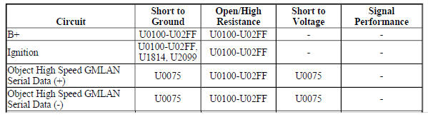
.jpg)
Circuit/System Description
The serial data circuit is the means by which the devices in the vehicle communicate with each other. Once the scan tool is connected to the serial data circuit through the Data Link Connector (DLC), the scan tool can be used to monitor each device for diagnostic purposes and to check for Diagnostic Trouble Codes (DTC). When the ignition switch is in RUN, each device communicating on the serial data circuit sends a state of health message to ensure that the device is operating properly. When a device stops communicating on the serial data circuit, for example if the device loses power or ground, the state of health message it normally sends on the serial data circuit disappears. Other devices on the serial data circuit, which expect to receive that state of health message, detect its absence; those devices in turn set a DTC associated with the loss of state of health of the non-communicating device. The DTC is unique to the device which is not communicating and one or more devices may set the same exact code. A loss of serial data communications DTC does not represent a failure of the devices that contain the stored code.
Conditions for Running the DTC
The system voltage is between 9-16 V.
Conditions for Setting the DTC
A supervised periodic message that includes the transmitter device availability has not been received.
Action Taken When the DTC Sets
- Specific subsystems will not function.
- DTC U0100 in the Transmission Control Module will cause the transmission to go into default gears.
- Both DTC U0100 in the Transmission Control Module and DTC U0101 in the Engine Control Module will cause the malfunction indicator lamp (MIL) to illuminate.
Conditions for Clearing the DTC
- The Engine Control Module or Transmission Control Module turns OFF the MIL after 4 consecutive ignition cycles that the diagnostic runs and does not fail.
- A current DTC clears when the malfunction is no longer present.
- A history DTC clears when the device ignition cycle counter reaches the reset threshold of 50, without a repeat of the malfunction.
Diagnostic Aids
Sometimes, while diagnosing a specific customer concern or after a repair, you may notice a history U code present. However, there is no associated "current" or "active" status. Loss of communication U codes such as these can set for a variety of reasons. Many times, they are transparent to the vehicle operator and technician, and/or have no associated symptoms. Eventually, they will erase themselves automatically after a number of fault-free ignition cycles. This condition would most likely be attributed to one of these scenarios:
- A device on the data communication circuit was disconnected while the communication circuit is awake.
- Power to one or more devices was interrupted during diagnosis.
- A low battery condition was present, so some devices stop communicating when battery voltage drops below a certain threshold.
- Battery power was restored to the vehicle and devices on the communication circuit did not all reinitialize at the same time.
- If a loss of communication U code appears in history for no apparent reason, it is most likely associated with one of the scenarios above. These are all temporary conditions and should never be interpreted as an intermittent fault, causing you to replace a part.
- A device may have a U code stored in history that does not require any repairs. Issues with late or corrupted messages between devices can be temporary with no apparent symptom or complaint; this does not mean the device is faulty. Do not replace a device based only on a history U code.
- Do not replace a device reporting a U code. The U code identifies which device needs to be diagnosed for a communication issue.
- Communication may be available between some devices and the scan tool with either the low or high speed GMLAN serial data system inoperative. This condition is due to those devices using multiple serial data communication systems.
- Use Data Link References to determine what serial data communications the device uses.
- Some devices may not have internal protection for specific control circuits and may open a B+ or ignition fuse. If a fuse is open and the B+ or ignition circuit is not shorted to ground, ensure none of the control circuits are shorted to ground before replacing the device.
- Some intermittent communication concerns may be caused by fretting corrosion on the serial data circuit terminals. Inspect all connectors at the device that set the communication DTC, the device that the communication DTC was set against, and any inline harness connectors between the two devices. Do not replace a device based only on fretting corrosion. Refer to bulletin 09-06-03-004 for assistance with the diagnosis and repair of this condition, if applicable.
- This diagnostic can be used for any device that is not communicating, regardless of the type of serial data circuit it is connected to, providing the vehicle is equipped with the device.
Reference Information
Schematic Reference
- Data Communication Schematics (Encore), Data Communication Schematics (Trax)
- Control Module References
Connector End View Reference
WIRING SYSTEMS AND POWER MANAGEMENT - COMPONENT CONNECTOR END VIEWS - INDEX - ENCORE WIRING SYSTEMS AND POWER MANAGEMENT - COMPONENT CONNECTOR END VIEWS - INDEX - TRAX
Description and Operation
Data Link Communications Description and Operation
Electrical Information Reference
- Circuit Testing
- Connector Repairs
- Testing for Intermittent Conditions and Poor Connections
- Wiring Repairs
Scan Tool Reference
Control Module References for scan tool information
Circuit/System Verification
- Determine the device that is not communicating. Refer to Control Module U Code List.
- Verify that DTC U0073, U2100, U0074, U0078, U1814, U2099, B1325, B1330, B1370, B1380, B1424, B1440, B1441, B1517, C0800, C0899, C12E1, P0560, or P0562 is not set.
If any of the DTCs are set
Refer to Diagnostic Trouble Code (DTC) List - Vehicle .
If none of the DTCs are set
- Verify that DTC U0125 and DTC U0126 are not set together.
If both of the DTCs are set together
Refer to Scan Tool Does Not Communicate with Chassis High Speed GMLAN Device.
If both of the DTCs are not set together
- Refer to Circuit/System Testing.
Circuit/System Testing
NOTE: Use the schematics and connector end views to identify the device's ground, B+, ignition, accessory wakeup serial data, serial data communication enable, and serial data circuit terminals.
- Ignition OFF, all access doors closed, all vehicle systems OFF, and all keys at least 3 m (9.8 ft) away from vehicle. It may take up to 2 min for all vehicle systems to power down. Disconnect all the harness connectors at the device that is not communicating.
- Test for less than 10 ohms between each ground circuit terminal and ground.
If 10 ohms or greater
- Ignition OFF.
- Test for less than 2 ohms in the ground circuit end to end.
- If 2 ohms or greater, repair the open/high resistance in the circuit.
- If less than 2 ohms, repair the open/high resistance in the ground connection.
If less than 10 ohms
- Ignition ON.
- If equipped, verify a test lamp illuminates between each B+ circuit terminal and ground.
If the test lamp does not illuminate and the circuit fuse is good
- Ignition OFF.
- Test for less than 2 ohms in the B+ circuit end to end.
- If 2 ohms or greater, repair the open/high resistance in the circuit.
- If less than 2 ohms, verify the fuse is not open and there is voltage at the fuse
If the test lamp does not illuminate and the circuit fuse is open
- Ignition OFF.
- Test for infinite resistance between the B+ circuit and ground.
- If less than infinite resistance, repair the short to ground on the circuit.
- If infinite resistance, replace the disconnected device.
If the test lamp does not illuminate and the circuit fuse is open
- If equipped, verify a test lamp illuminates between each ignition circuit terminal and ground.
If the test lamp does not illuminate and the circuit fuse is good
- Ignition OFF.
- Test for less than 2 ohms in the ignition circuit end to end.
- If 2 ohms or greater, repair the open/high resistance in the circuit.
- If less than 2 ohms, verify the fuse is OK and there is voltage at the fuse.
If the test lamp does not illuminate and the circuit fuse is open
- Ignition OFF.
- Test for infinite resistance between the ignition circuit and ground.
- If less than infinite resistance, repair the short to ground on the circuit.
- If infinite resistance, replace the disconnected device.
If the test lamp illuminates
- If equipped, verify a test lamp illuminates between each ignition circuit terminal, which is controlled by a control module, and ground.
If the test lamp does not illuminate
- Ignition OFF, disconnect the harness connectors at the control module that controls the ignition circuit.
- Test for infinite resistance between the ignition circuit and ground.
- If less than infinite resistance, repair the short to ground on the circuit.
- If infinite resistance
- Test for less than 2 ohms in the ignition circuit end to end.
- If 2 ohms or greater, repair the open/high resistance in the circuit.
- If less than 2 ohms, replace the control module that controls the ignition circuit.
If the test lamp illuminates
- Test for less than 4.5 V between each GMLAN serial data circuit terminal and ground.
- If 4.5 V or greater between a low speed GMLAN serial data circuit and ground
Refer to Scan Tool Does Not Communicate with Low Speed GMLAN Device to test for a short to voltage.
- If 4.5 V or greater between a high speed GMLAN serial data circuit and ground
Refer to Scan Tool Does Not Communicate with High Speed GMLAN Device to test for a short to voltage.
- If less than 4.5 V
- Ignition OFF, all access doors closed, all vehicle systems OFF, and all keys at least 3 m (9.8 ft) away from vehicle. It may take up to 2 min for all vehicle systems to power down.
- Test for greater than 100 ohms between each GMLAN serial data circuit terminal and ground.
- If 100 ohms or less between a low speed GMLAN serial data circuit and ground
Refer to Scan Tool Does Not Communicate with Low Speed GMLAN Device to test for a short to ground.
- If 100 ohms or less between a high speed GMLAN serial data circuit and ground
Refer to Scan Tool Does Not Communicate with High Speed GMLAN Device to test for a short to ground.
If greater than 100 ohms
- Test for less than 2 ohms in each of the GMLAN serial data circuits end to end between the device harness connector and the X84 Data Link Connector terminals listed below
- Low speed GMLAN serial data circuit terminal 1
- High speed GMLAN serial data circuit terminal 6 or 14
- Mid speed GMLAN serial data circuit terminal 3 or 11
- Chassis high speed GMLAN serial data circuit terminal 12 or 13
- Object high speed GMLAN serial data circuit terminal 3 or 11
If 2 ohms or greater
Repair the open/high resistance in the serial data circuit between the non communicating device and the device setting the DTC or a serial data splice pack.
If less than 2 ohms
NOTE: The following test step is only applicable to a high speed GMLAN device with 2 pairs of serial data circuits or a high speed GMLAN device with an internal terminating resistor.
- Test for 110-130 ohms between each pair of high speed GMLAN serial data circuits.
If less than 110 ohms
Refer to Scan Tool Does Not Communicate with High Speed GMLAN Device to test for a short to ground or a short between the serial data circuits.
If greater than 130 ohms
Refer to Scan Tool Does Not Communicate with High Speed GMLAN Device to test for an open/high resistance in the serial data circuit.
If between 110-130 ohms
- Replace the device that is not communicating.
Repair Instructions
Perform the Diagnostic Repair Verification after completing the repair.
- GMLAN and Media Oriented Systems Transport (MOST) Wiring Repairs
- Control Module References for device replacement, programming and setup
READ NEXT:
 DTC U0300-U0336: See control module u code list
Diagnostic Instructions
Perform the Diagnostic System Check - Vehicle prior to using this
diagnostic procedure.
Review Strategy Based Diagnosis for an overview of the diagnostic
approach.
Diag
DTC U0400-U05FF: See control module U code list
Diagnostic Instructions
Perform the Diagnostic System Check - Vehicle prior to using this
diagnostic procedure.
Review Strategy Based Diagnosis for an overview of the diagnostic
approach.
Diag
DTC U1814: Powertrain wake-up communication circuit
Diagnostic Instructions
Perform the Diagnostic System Check - Vehicle prior to using this
diagnostic procedure.
Review Strategy Based Diagnosis for an overview of the diagnostic
approach.
Diag
SEE MORE:
Automotive terminology & definitions
ACTIVE SUSPENSION SYSTEM
active suspension systems move each wheel up and down to control body motion
in response to road
abnormalities. The system responds to inputs from the road and the driver. With
an active suspension, a
vehicle can simultaneously provide the smooth ride of a soft suspension
DTC B242A (WITHOUT MEMORY A45): Seat heaters common circuit
Diagnostic Instructions
Perform the Diagnostic System Check - Vehicle prior to using this
diagnostic procedure.
Review Strategy Based Diagnosis for an overview of the diagnostic
approach.
Diagnostic Procedure Instructions provides an overview of each diagnostic
category.
DTC Descriptors
D
