Chevrolet Trax: DTC P2199
Diagnostic Instructions
- Perform the Diagnostic System Check - Vehicle prior to using this diagnostic procedure.
- Review Strategy Based Diagnosis for an overview of the diagnostic approach.
- Diagnostic Procedure Instructions provides an overview of each diagnostic category.
DTC Descriptor
DTC P2199
Intake Air Temperature (IAT) Sensors 1-2 Not Plausible
Diagnostic Fault Information
IAT Sensor 1
.jpg)
IAT Sensor 2
.jpg)
Typical Scan Tool Data
IAT Sensor 1
.jpg)
IAT Sensor 2
.jpg)
.jpg)
Circuit/System Description
The sensors listed below are integrated within the multifunction intake air sensor:
- IAT sensor 1
- IAT sensor 2
- Humidity sensor
- MAF sensor
- BARO pressure sensor
The intake air temperature (IAT) sensor 1 is a variable resistor that changes the voltage on the engine control module (ECM) supplied 5 V signal circuit. The signal varies with inlet air temperature in the sensor bore and is displayed by the scan tool as ºC (ºF). The IAT sensor 2 and the humidity sensor share the same circuit. The IAT sensor 2 signal is displayed by the scan tool as Hz (Hertz) and ºC (ºF).
The IAT sensor 1 produces an analog signal on pin-8 of the sensor. The IAT sensor 2 produces a frequency modulated signal on pin-1 of the sensor.
The sensors listed below share an ECM supplied 5 V reference circuit:
- IAT sensor 2
- Humidity sensor
- Barometric pressure (BARO) sensor
The sensors listed below share an ECM supplied low reference circuit:
- IAT sensor 1
- IAT sensor 2
- Humidity sensor
- Barometric pressure (BARO) sensor
IAT Sensor 1 - Temperature, Resistance, Voltage Table
.jpg)
IAT Sensor 2 - Temperature, Frequency Table
.jpg)

Conditions for Running the DTC
- DTC P1682 is not set.
- The ignition is ON.
- Ignition voltage is at least 11 V.
- This DTC runs continuously within the enabling conditions.
Conditions for Setting the DTC
The ECM detects that the absolute difference between the IAT sensor 1 and the IAT sensor 2 temperatures is greater than 55ºC (99ºF) for longer than 5 s.
Action Taken When the DTC Sets
DTC P2199 is a Type B DTC.
Conditions for Clearing the MIL/DTC
DTC P2199 is a Type B DTC.
Diagnostic Aids
- With the ignition ON, when the engine is OFF and is cold; properly functioning IAT sensors 1 and 2 will gradually increase the scan tool IAT Sensor 1 and 2 parameters. This is due to the heat that is generated by the multifunction intake air sensor internal heating elements.
- The Humidity sensor and the IAT sensor 2 signals are sent to the ECM on the same circuit. If the IAT Sensor 2 parameter displays the values: 10 Hz; -40ºC (-40ºF), and there are also Humidity Sensor DTCs, check for a circuit problem.
Reference Information
Schematic Reference
Engine Controls Schematics (Encore) , Engine Controls Schematics (Trax)
Connector End View Reference
WIRING SYSTEMS AND POWER MANAGEMENT - COMPONENT CONNECTOR END VIEWS - INDEX - ENCORE WIRING SYSTEMS AND POWER MANAGEMENT - COMPONENT CONNECTOR END VIEWS - INDEX - TRAX
Electrical Information Reference
- Circuit Testing
- Connector Repairs
- Testing for Intermittent Conditions and Poor Connections
- Wiring Repairs
DTC Type Reference
Powertrain Diagnostic Trouble Code (DTC) Type Definitions (LUV) , Powertrain Diagnostic Trouble Code (DTC) Type Definitions (2H0)
Scan Tool Reference
Control Module References for scan tool information
Special Tools
EL-38522-A Variable Signal Generator
For equivalent regional tools, refer to Special Tools (Diagnostic Tools) .
Circuit/System Verification
- Ignition ON.
- Verify that DTC DTC P0641, P0651, P0697, or P06A3 is not set.
- If any of the DTCs are set
Refer to DTC P0641, P0651, P0697, or P06A3 (ECM) for further diagnosis.
- If none of the DTCs are set
NOTE: To minimize the effects of residual engine heat and sensor internal heating elements, perform Steps 3 and 4 of this verification procedure only if the ignition has been OFF for 8 hours or more.
- Ignition ON.
- Verify the following scan tool parameters are within 25ºC (45ºF) of each other.
- Start-Up IAT Sensor 1
- IAT Sensor 2
- IAT Sensor 3; where equipped
- If not within 25ºC (45ºF)
Refer to Circuit/System Testing.
- If within 25ºC (45ºF)
- Engine idling, verify the following scan tool parameters are between: -38 and +149ºC (-36 and +300ºF).
- IAT Sensor 1
- IAT Sensor 2
- IAT Sensor 3; where equipped
- If not between: -38 and +149ºC (-36 and +300ºF)
Refer to Circuit System Testing.
- If between: -38 and +149ºC (-36 and +300ºF)
- Operate the vehicle within the conditions for running the DTC. You may also operate the vehicle within the conditions that you observed from the freeze frame/failure records data.
- Verify the DTC does not set.
- If the DTC sets
Refer to Circuit/System Testing.
- If the DTC does not set
- All OK
Circuit/System Testing
NOTE: You must perform the Circuit/System Verification before proceeding with Circuit/System Testing.
- Ignition OFF, and all vehicle systems OFF, it may take up to 2 min. for all vehicle systems to power down. Disconnect the harness connector at the B75C Multifunction Intake Air sensor.
- Test for less than 2 ohms between the low reference circuit terminal 7 and ground.
- If 2 ohms or greater
- Ignition OFF, disconnect the harness connector at the K20 Engine Control Module.
- Test for less than 2 ohms in the low reference circuit end to end.
- If 2 ohms or greater, repair the open or high resistance in the circuit.
- If less than 2 ohms replace the K20 Engine Control Module.
- If less than 2 ohms
- Ignition ON, test for 4.8-5.2 V between the 5 V reference circuit terminal 2 and ground.
- If less than 4.8 V
- Ignition OFF, disconnect the harness connector at the K20 Engine Control Module.
- Test for infinite resistance between the signal circuit and ground.
- If less than infinite resistance, repair the short to ground on the circuit.
- If infinite resistance
- Test for less than 2 ohms in the signal circuit end to end.
- If 2 ohms or greater, repair the open/high resistance in the circuit.
- If less than 2 ohms, replace the K20 Engine Control Module.
- If greater than 5.2 V
NOTE: If the 5 V reference circuit is shorted to a voltage the engine control module or the sensor may be damaged.
- Ignition OFF, disconnect the harness connector at the K20 Engine Control Module.
- Ignition ON, test for less than 1 V between the 5 V reference circuit and ground.
- If 1 V or greater, repair the short to voltage on the circuit.
- If less than 1 V, replace the K20 Engine Control Module.
- If between 4.8-5.2 V
- Ignition ON, test for 4.8-5.2 V between the signal circuit terminal 8 and ground.
- If less than 4.8 V
- Ignition OFF, disconnect the harness connector at the K20 Engine Control Module.
- Test for infinite resistance between the signal circuit and ground.
- If less than infinite resistance, repair the short to ground on the circuit.
- If infinite resistance
- Test for less than 2 ohms in the signal circuit end to end.
- If 2 ohms or greater, repair the open/high resistance in the circuit.
- If less than 2 ohms, replace the K20 Engine Control Module.
- If greater than 5.2 V
NOTE: If the signal circuit is shorted to a voltage the engine control module or the sensor may be damaged.
- Ignition OFF, disconnect the harness connector at the K20 Engine Control Module.
- Ignition ON, test for less than 1 V between the signal circuit and ground.
- If 1 V or greater, repair the short to voltage on the circuit.
- If less than 1 V, replace the K20 Engine Control Module.
- If between 4.8-5.2 V
- Ignition ON, verify the scan tool IAT Sensor 1 parameter is colder than -39ºC (-38ºF).
- If warmer than -39ºC (-38ºF).
- Ignition OFF, disconnect the harness connector at the K20 Engine Control Module.
- Test for infinite resistance between the signal circuit terminal 8 and ground.
- If less than infinite resistance, repair the short to ground on the circuit.
- If infinite resistance
- Test for less than 2 ohms in the signal circuit end to end.
- If 2 ohms or greater, repair the open/high resistance in the circuit.
- If less than 2 ohms, replace the K20 Engine Control Module.
- If colder than -39ºC (-38ºF).
- Ignition OFF, install a 3 A fused jumper wire between the signal circuit terminal 8 and the low reference circuit terminal 7.
- Verify the scan tool IAT Sensor 3 parameter is warmer than 150ºC (302ºF).
- If colder than 150ºC (302ºF).
- Ignition OFF, remove the jumper wire, disconnect the harness connector at the K20 Engine Control Module, ignition ON.
- Test for less than 1 V between the signal circuit and ground.
- If 1 V or greater, repair the short to voltage on the circuit.
- If less than 1 V
- Ignition OFF.
- Test for less than 2 ohms in the signal circuit end to end.
- If 2 ohms or greater, repair the open/high resistance in the circuit.
- If less than 2 ohms, replace the K20 Engine Control Module.
- If warmer than 150ºC (302ºF).
- Ignition ON, test for 4.8-5.2 V between the signal terminal 1 and ground.
- If less than 4.8 V
- Ignition OFF, disconnect the harness connector at the K20 Engine Control Module.
- Test for infinite resistance between the signal circuit and ground.
- If less than infinite resistance, repair the short to ground on the circuit.
- If infinite resistance
- Test for less than 2 ohms in the signal circuit end to end.
- If 2 ohms or greater, repair the open/high resistance in the circuit.
- If less than 2 ohms, replace the K20 Engine Control Module.
- If greater than 5.2 V
NOTE: If the signal circuit is shorted to a voltage the engine control module or the sensor may be damaged.
- Ignition OFF, disconnect the harness connector at the K20 Engine Control Module.
- Ignition ON, test for less than 1 V between the signal circuit and ground.
- If 1 V or greater, repair the short to voltage on the circuit.
- If less than 1 V, replace the K20 Engine Control Module.
- If between 4.8-5.2 V
- Determine if EL-38522-A Variable Signal Generator or equivalent is available.
- EL-38522-A, Variable Signal Generator; or equivalent is not available
- Replace the K20 Engine Control Module.
- Operate the vehicle within the Conditions for Running the DTC. You may also operate the vehicle within the conditions that you observed from the freeze frame/failure records data.
- Verify the DTC does not set.
- If the DTC sets
Refer to Step 13.
- If no DTCs set
- All OK.
- EL-38522-A, Variable Signal Generator; or equivalent is available
- Ignition OFF, connect the leads of the EL-38522-A Variable Signal Generator as follows:
- Red lead to the signal circuit terminal 1 at the harness connector
- Black leads to ground
- Battery voltage supply lead to B+
- Set the EL-38522-A Variable Signal Generator to the following specifications.
- Signal switch to 5 V
- Duty Cycle switch to 50 % (Normal)
- Frequency switch to 30 Hz
- Ignition ON, verify the scan tool IAT Sensor 2 parameter is between 28-32 Hz.
- If not between 28-32 Hz
Replace the K20 Engine Control Module.
- If between 28-32 Hz
- Test or replace the appropriate temperature sensor.
Component Testing
Multifunction Intake Air Sensor
- Ignition OFF, disconnect the harness connector at the B75C Multifunction Intake Air sensor.
NOTE: A thermometer can be used to test the sensor off the vehicle.
- Test the IAT sensor 1 by varying the sensor temperature while monitoring the sensor resistance. Compare the readings with the Temperature Versus Resistance - Intake Air Temperature Sensor (Bosch Sensor) , Temperature Versus Resistance - Intake Air Temperature Sensor (Delco Sensor) table for Bosch Sensors. The resistance values should be in range of the table values.
- If not within the specified range.
Replace the B75C Multifunction Intake Air sensor.
- If within the specified range.
- All OK
Multifunction Intake Air Sensor
- Test the IAT Sensor 2 by varying the sensor temperature while monitoring the air temperature with a thermometer. Compare the readings with the scan tool IAT Sensor 2 parameter. The values should be within 5%.
- If not within 5%
Replace the B75C Multifunction Intake Air sensor.
- If within 5%
- All OK.
Repair Instructions
Perform the Diagnostic Repair Verification after completing the repair.
- Mass Airflow Sensor Replacement for multifunction intake air sensor replacement
- Control Module References for Engine Control Module replacement, programming, and setup.
DTC P219A
Diagnostic Instructions
- Perform the Diagnostic System Check - Vehicle prior to using this diagnostic procedure.
- Review Strategy Based Diagnosis for an overview of the diagnostic approach.
- Diagnostic Procedure Instructions provides an overview of each diagnostic category.
DTC Descriptor
DTC P219A
Fuel Trim Cylinder Balance
Circuit/System Description
The Air Fuel Imbalance diagnostic detects a rich or lean cylinder to cylinder air/fuel ratio imbalance. The diagnostic monitors the pre-catalyst heated oxygen sensor (HO2S) signal's frequency and amplitude characteristics by calculating an accumulated voltage over a predetermined sample period. An imbalance is indicated when multiple samples of the accumulated voltage are consistently higher than the desired value.
Conditions for Running the DTC
- DTCs P0016, P0017, P0068, P0101, P0102, P0103, P0106, P0107, P0108, P0116, P0117, P0118, P0122, P0123, P0128, P0201-P0204, P0222, P0223, P0261, P0262, P0264, P0265, P0267, P0268, P0270, P0271, P0300, P0301-P0304, P0340, P0341, P0365, P0366, P0411, P0442, P0455, P0458, P0496, P1248, P1249, P124A, P124B, P16F3, P2101, P2135, P2147, P2148, P2150. P2151, P2153, P2154, P2156, P2157, P2440, P2444 are not set.
- The EVAP device control and intrusive diagnostics are not active.
- The engine overspeed protection is not active.
- The engine is in closed loop status.
- The system voltage is greater than 11 V.
- The engine coolant temperature (ECT) is warmer than -20ºC (-4ºF).
- The engine speed is between 900-6,000 RPM.
- The mass air flow is between 12-500 g/s.
- The AIR pump is not ON.
- Engine run time is greater than 130 s.
- Fuel level is greater than 10% and no fuel level sensor fault is present.
- The DTC runs continuously when the above conditions have been met.
Conditions for Setting the DTC
Multiple samples of the pre-catalyst HO2S accumulated voltage are consistently greater than the desired value
Action Taken When the DTC Sets
DTC P219A is a Type A DTC.
Conditions for Clearing the MIL/DTC
DTC P219A is a Type A DTC.
Diagnostic Aids
- The air fuel imbalance diagnostic is very sensitive to heated oxygen sensor (HO2S) design. A non-OE sensor or an incorrect part number may cause a DTC to set.
- Monitoring the misfire current counters, or misfire graph, may help to isolate the cylinder that is causing the condition.
- Certain aftermarket air filters may cause a DTC to set.
- Certain aftermarket air induction systems or modifications to the air induction system may cause a DTC to set.
- Certain aftermarket exhaust system components may cause a DTC to set.
Reference Information
Schematic Reference
Engine Controls Schematics (Encore) , Engine Controls Schematics (Trax)
Connector End View Reference
WIRING SYSTEMS AND POWER MANAGEMENT - COMPONENT CONNECTOR END VIEWS - INDEX - ENCORE WIRING SYSTEMS AND POWER MANAGEMENT - COMPONENT CONNECTOR END VIEWS - INDEX - TRAX
Component View Reference
Powertrain Component Views
Electrical Information Reference
- Circuit Testing
- Troubleshooting with a Test Lamp
- Testing for Intermittent Conditions and Poor Connections
- Wiring Repairs
- Connector Repairs
DTC Type Reference
Powertrain Diagnostic Trouble Code (DTC) Type Definitions (LUV) , Powertrain Diagnostic Trouble Code (DTC) Type Definitions (2H0)
Scan Tool Reference
Control Module References for scan tool information
Circuit/System Verification
- Ignition ON.
- Verify no other DTCs are set.
- If any other DTCs are set
Refer to Diagnostic Trouble Code (DTC) List - Vehicle for further diagnosis.
- If no other DTCs are set
- Verify DTC P219A is not set.
- If a DTC is set
Refer to Circuit/System Testing.
- If no DTC is set
- Operate the vehicle within the Conditions for Running the DTC. You may also operate the vehicle within the conditions that you observed in the Freeze Frame/Failure Records data.
- Verify DTC P219A is not set.
- If a DTC is set
Refer to Circuit/System Testing.
- If no DTC is set
- All OK.
Circuit/System Testing
- Engine idling, verify the manifold absolute pressure (MAP) sensor parameter is between 20-48 kPa
- If not within the specified range .
Refer to DTC P0106 , or DTC P0107 or P0108 .
- If within the specified range, verify that none of the conditions listed below exist:
- Modified, damaged, leaking, or restricted air induction system components.
- Improper operation of the crankcase ventilation system.
- Split, kinked, or improperly connected vacuum hoses.
- Restricted, damaged, leaking, or modified exhaust system from the catalytic converter forward.
- Refer to Symptoms - Engine Exhaust .
- Improperly operating fuel injectors. Refer to Fuel Injector Diagnosis.
- Contaminated fuel. Refer to Alcohol/Contaminants-in-Fuel Diagnosis.
- Excessive fuel in the crankcase due to leaking injectors. Change engine oil as necessary.
- Improper ignition system operation. Refer to Electronic Ignition System Diagnosis.
- If a condition is found
Repair as necessary.
- If no condition is found
- Test the engine for any mechanical conditions such as sticking valves, lifters, etc., which could alter the flow into the combustion chamber. Refer to Symptoms - Engine Mechanical
Repair Instructions
Perform the Diagnostic Repair Verification after completing the repair.
Reset the fuel trim after completing the repair.
DTC P2227-P2230
Diagnostic Instructions
- Perform the Diagnostic System Check - Vehicle prior to using this diagnostic procedure.
- Review Strategy Based Diagnosis for an overview of the diagnostic approach.
- Diagnostic Procedure Instructions provides an overview of each diagnostic category.
DTC Descriptors
DTC P2227
Barometric Pressure (BARO) Sensor Performance
DTC P2228
Barometric Pressure (BARO) Sensor Circuit Low Voltage
DTC P2229
Barometric Pressure (BARO) Sensor Circuit High Voltage
DTC P2230
Barometric Pressure (BARO) Sensor Circuit Erratic - (If used)
Diagnostic Fault Information

Typical Scan Tool Data
BARO
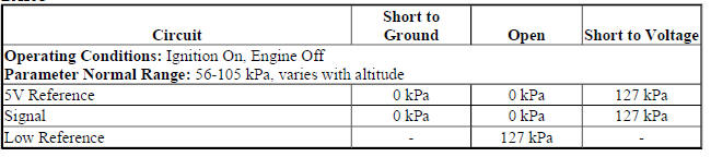
Circuit/System Description
The barometric pressure (BARO) sensor responds to changes in altitude and atmospheric conditions. This gives the engine control module (ECM) an indication of barometric pressure. The ECM uses this information to calculate fuel delivery. The BARO sensor provides a voltage signal to the ECM relative to the atmospheric pressure changes. The ECM monitors the BARO sensor signal for a voltage outside of the normal range.
Conditions for Running the DTC
P2227
- DTCs P0068, P0101, P0102, P0103, P0106, P0107, P0108, P0112, P0113, P0117, P0118, P0121, P0122, P0123, P0222, P0223, P1516, P2135, P2228 and P2229 are not set.
- Engine is running.
OR
- DTCs P0106, P0107, P0108, P2228, P2229 and P2230 are not set and are not pending.
- Ignition On, engine Off.
- DTC P2227 runs continuously when the above conditions are met.
P2228 or P2229
- The engine is running.
- The DTCs run continuously when the above condition is met .
P2230
- The engine is running.
- DTCs P0068, P0101, P0102, P0103, P0106, P0107, P0108, P0112, P0113, P0117, P0118, P0121, P0122, P0123, P0222, P0223, P1516, P2135, P2228 and P2229 are not set.
- DTC P2230 runs continuously when the above conditions are met.
Conditions for Setting the DTC
P2227
- Engine running, the ECM detects that the difference between the BARO signal and the calculated BARO is greater than 15 kPa (2.17 PSI) when the vehicle has traveled no more than 0.1 km (0.06 mi) since the last calculated BARO update, or if the difference is greater than 25 kPa (3.62 PSI) when the vehicle has traveled greater than 0.1 km (0.06 mi) since the last calculated BARO update.
- Ignition On, engine Off, the ECM detects that the BARO pressure is less than 50 kPa (7.25 PSI) or greater than 115 kPa (16.76 PSI).
P2228
The ECM detects that the BARO sensor voltage is less than 2 V.
P2229
The ECM detects that the BARO sensor voltage is greater than 4.5 V.
P2230
The ECM detects that the difference between the current BARO sensor reading and the previous BARO sensor reading is greater than 10 kPa (1.45 PSI).
Action Taken When the DTC Sets
DTCs P2227, P2228, P2229, and P2230 are Type B DTCs.
Conditions for Clearing the DTC
DTCs P2227, P2228, P2229, and P2230 are Type B DTCs.
Diagnostic Aids
Inspect the inlet port on the Barometric Pressure Sensor for moisture or debris and attempt to dry or clean the inlet, if contaminated.
Reference Information
Schematic Reference
Engine Controls Schematics (Encore) , Engine Controls Schematics (Trax)
Connector End View Reference
WIRING SYSTEMS AND POWER MANAGEMENT - COMPONENT CONNECTOR END VIEWS - INDEX - ENCORE WIRING SYSTEMS AND POWER MANAGEMENT - COMPONENT CONNECTOR END VIEWS - INDEX - TRAX
Electrical Information Reference
- Circuit Testing
- Connector Repairs
- Testing for Intermittent Conditions and Poor Connections
- Wiring Repairs
DTC Type Reference
Powertrain Diagnostic Trouble Code (DTC) Type Definitions (LUV) , Powertrain Diagnostic Trouble Code (DTC) Type Definitions (2H0)
Scan Tool Reference
Control Module References for scan tool information
Circuit/System Verification
- Ignition On.
- Verify DTC P0106, P0107, P0108, P0641, P0651, or P0697 is not set.
- If any of the DTCs are set
Refer to Diagnostic Trouble Code (DTC) List - Vehicle .
- If none of the DTCs are set
- Verify the scan tool MAP Sensor parameter is within the range specified in the Altitude Versus Barometric Pressure table.
- If not within the specified range
Refer to DTC P0106 .
- If within the specified range
- Verify the scan tool BARO pressure parameter is within the range specified in the Altitude Versus Barometric Pressure table.
- If the BARO is not within the specified range
Refer to Circuit/System Testing.
- If the BARO is within the specified range
- Operate the vehicle within the Conditions for Running the DTC. You may also operate the vehicle within the conditions that you observed in the Freeze Frame/Failure Records data.
- Verify the DTC does not set.
- If the DTC sets
Refer to Circuit/System Testing.
- If the DTC does not set
- All OK.
Circuit/System Testing
- Verify the conditions listed below do not exist with the B75C Multifunction Intake Air Sensor:
- Damage
- Restrictions in the inlet port
- If a condition exists
Repair or replace the B75C Multifunction Intake Air Sensor as necessary.
- If none of the conditions exist
- Ignition Off, and all vehicle systems Off, it may take up to 2 minutes for all vehicle systems to power down. Disconnect the harness connector at the B75C Multifunction Intake Air Sensor.
- Test for less than 5 ohms between the low reference circuit terminal 7 and ground.
- If 5 ohms or greater
- Ignition Off, disconnect the harness connector at the K20 Engine Control Module.
- Test for less than 2 ohms in the low reference circuit end to end.
- If greater than the specified value, repair the open or high resistance in the circuit.
- If 2 ohms or less replace the K20 Engine Control Module.
- If less than 5 ohms
- Ignition On.
- Test for 4.8-5.2 V between the 5 V reference circuit terminal 2 and ground.
- If less than 4.8 V
- Ignition Off, disconnect the harness connector at the K20 Engine Control Module.
- Test for infinite resistance between the 5 V reference circuit and ground.
- If less than infinite resistance, repair the short to ground on the circuit.
- If infinite resistance
- Test for less than 2 ohms in the 5 V reference circuit end to end.
- If 2 ohms or greater, repair the open/high resistance in the circuit.
- If less than 2 ohms, replace the K20 Engine Control Module.
- If greater than 5.2 V
- Ignition Off, disconnect the harness connector at the K20 Engine Control Module, ignition On.
- Test for less than 1 V between the 5 V reference circuit and ground.
- If 1 V or greater, repair the short to voltage on the circuit.
- If less than 1 V, replace the K20 Engine Control Module.
- If between 4.8-5.2 V
- Verify the scan tool BARO Sensor parameter is less than 0.2 V.
If 0.2 V or greater
- Ignition Off, disconnect the harness connector at the K20 Engine Control Module, ignition On.
- Test for less than 1 V between the signal circuit terminal 6 and ground.
- If 1 V or greater, repair the short to voltage on the circuit.
- If less than 1 V, replace the K20 Engine Control Module.
- If less than 0.2 V
- Install a 3 A fused jumper wire between the signal circuit terminal 6 and the 5 V reference circuit terminal 2.
- Verify the scan tool BARO Sensor parameter is greater than 4.5 V.
If 4.5 V or less
- Ignition Off, remove the jumper wire, disconnect the harness connector at the K20 Engine Control Module.
- Test for infinite resistance between the signal circuit terminal 6 and ground.
- If less than infinite resistance, repair the short to ground on the circuit.
- If infinite resistance
- Test for less than 2 ohms in the signal circuit end to end.
- If 2 ohms or greater, repair the open/high resistance in the circuit.
- If less than 2 ohms, replace the K20 Engine Control Module.
- If greater than 4.5 V
- Test or replace the B75C Multifunction Intake Air Sensor.
Repair Instructions
Perform the Diagnostic Repair Verification after completing the repair.
- Mass Airflow Sensor Replacement for multifunction intake air sensor replacement
- Control Module References for engine control module replacement, programming and setup
DTC P2261
Diagnostic Instructions
- Perform the Diagnostic System Check - Vehicle prior to using this diagnostic procedure.
- Review Strategy Based Diagnosis for an overview of the diagnostic approach.
- Diagnostic Procedure Instructions provides an overview of each diagnostic category.
DTC Descriptor
DTC P2261
Turbocharger Bypass Valve Stuck
Circuit/System Description
The turbocharger incorporates a bypass valve which is controlled by the Engine Control Module (ECM), by utilizing a remotely mounted solenoid valve, to prevent turbocharger surging and damage from vibrations by opening during abrupt closed throttle conditions. When the valve is open during closed throttle deceleration conditions, it allows the air to recirculate in the turbocharger and maintain turbocharger speed. Within a calibrated range during the closed throttle event, or upon a wide open throttle command the valve will then close to optimize turbo response. The bypass solenoid valve has the following circuits:
- Ignition voltage
- Turbocharger bypass solenoid valve control
As engine load and engine speed increases, the turbocharger bypass solenoid valve remains commanded ON by the ECM. As soon as the throttle closes the turbocharger bypass solenoid valve is commanded OFF by the ECM, in order to allow the turbocharger bypass valve to open and allow the turbocharger air to recirculate, there by preventing turbocharger surging.
Conditions for Running the DTC
- DTCs P0033, P0034, P0035, P0097, P0098, P0100, P0101, P0102, P0103, P0121, P0122, P0123, P0221, P0222, P0223, P0234, P0237, P0238, P0299, P2228, or P2229, are not set.
- The boost pressure versus the barometric pressure (BARO) ratio is between 1.1-3.3.
- The charge air bypass valve has been commanded ON for greater than 1 s immediately after an abrupt closed throttle has occurred and the resulting pressure ratio across the compressor exceeds the calibrated pressure ratio limit.
- The engine speed is greater than 1,800 RPM.
- This DTC runs continuously within the enabling conditions.
Conditions for Setting the DTC
The ECM has detected a series of pulsations in the induction system that exceed a calibrated threshold.
Action Taken When the DTC Sets
DTC P2261 is a Type B DTC.
Conditions for Clearing the DTC
DTC P2261 is a Type B DTC.
Reference Information
Schematic Reference
Engine Controls Schematics (Encore) , Engine Controls Schematics (Trax)
Connector End View Reference
WIRING SYSTEMS AND POWER MANAGEMENT - COMPONENT CONNECTOR END VIEWS - INDEX - ENCORE WIRING SYSTEMS AND POWER MANAGEMENT - COMPONENT CONNECTOR END VIEWS - INDEX - TRAX
Description and Operation
Turbocharger System Description
Electrical Information Reference
- Circuit Testing
- Connector Repairs
- Testing for Intermittent Conditions and Poor Connections
- Wiring Repairs
DTC Type Reference
Powertrain Diagnostic Trouble Code (DTC) Type Definitions (LUV) , Powertrain Diagnostic Trouble Code (DTC) Type Definitions (2H0)
Scan Tool Reference
Control Module References for scan tool information
Circuit/System Verification
- Ignition ON.
- Verify DTC P0033, P0034, or P0035 is not set.
- If any of the DTCs are set
Refer to DTC P0033-P0035 .
- If none of the DTCs are set
- Verify the scan tool BARO Sensor parameter is within the range specified in the Altitude Versus Barometric Pressure table for the current testing altitude.
- If the parameter is not within the range specified in the table
Refer to DTC P2227-P2230.
- If the parameter is within the range specified in the table
- Verify the scan tool Boost Pressure Sensor and BARO Sensor parameters are within 3 kPa (0.4 psi).
- If the parameters are not within 3 kPa (0.4 psi)
Refer to DTC P0236 .
- If the parameters are within 3 kPa (0.4 psi)
- Verify a click is heard or felt from the Q40 Turbocharger Bypass Solenoid Valve when commanding the Turbocharger Bypass Solenoid Valve ON and OFF with a scan tool.
- If a click is not heard or felt
Refer to Circuit/System Testing.
- If a click is heard or felt
- Operate the vehicle within the Conditions for Running the DTC. You may also operate the vehicle within the conditions that you observed from the Freeze Frame/Failure Records data.
- Verify a DTC does not set.
- If a DTC sets
Refer to Circuit/System Testing.
- If a DTC does not set
- All OK
Circuit/System Testing
- Verify the conditions listed below do not exist:
- Vacuum leaks
- Vacuum line restrictions
- Improper routing or connecting of the vacuum hoses on the Q40 Turbocharger Bypass Solenoid Valve, the bypass valve, and the bypass valve vacuum reservoir
- If a condition exists
Repair or replace the component as necessary.
- If none of the conditions exist
- Disconnect the Q40 Turbocharger Bypass Solenoid Valve vacuum supply hose at the intake manifold.
- Connect the GE 23738-A to the manifold.
NOTE: Allow engine idle to stabilize before continuing.
- Engine Idling, verify the vacuum gauge displays between 45-67 kPa (13-20 inches Hg) of vacuum.
- If not within the specified range
Repair the vacuum source.
- If within the specified range
NOTE: The vacuum reservoir (tank) is integral to intake manifold and is located at the bottom of the manifold.
- Ignition OFF, disconnect the vacuum hose at the turbocharger vacuum reservoir.
- Connect the GE 23738-A to the vacuum reservoir and apply 34 kPa (10 inches Hg) of vacuum.
- Verify the reservoir holds vacuum for at least 10 s.
- If the vacuum is not held for at least 10 s
Replace the intake manifold
- If the vacuum is held for at least 10 s
- Connect the vacuum hose to the reservoir.
NOTE: Disconnect the Q40 Turbocharger Bypass Solenoid Valve vacuum supply hose at the intake manifold if not still disconnected from step 2.
- Disconnect the vacuum hose at the turbocharger bypass valve and connect the GE 23738-A to the hose.
- Engine idling, command the Turbocharger Bypass Solenoid Valve ON and OFF with a scan tool.
- Verify the vacuum toggles between 0 kPa (0 inches Hg) to greater than 45 kPa (13 inches Hg).
- If not within the specified range
Test or replace the Q40 turbocharger bypass solenoid valve
- If within the specified range
- Connect any hoses that were disconnected during previous steps.
- Verify damage to the turbocharger bypass valve assembly does not exist. Refer to Turbocharger Cleaning and Inspection .
- If the turbocharger bypass valve assembly is damaged
Repair or replace the turbocharger bypass valve assembly as necessary.
- If the turbocharger bypass valve assembly is not damaged
- Replace the turbocharger.
Component Testing
Static Test
- Ignition OFF, disconnect the harness connector at the Q40 Turbocharger Bypass Solenoid Valve.
- Test for 20-27 ohms between terminal 1 and terminal 2 of the solenoid valve.
- If not between 20-27 ohms
Replace the Q40 Turbocharger Bypass Solenoid Valve.
- If between 20-27 ohms
- All OK
Dynamic Test
- Install a 10 A fused jumper wire between the Ignition terminal 2 and 12 V. Install a jumper wire between the control terminal 1 and ground.
- Verify the solenoid clicks.
- If the solenoid does not click
Replace the Q40 Turbocharger Bypass Solenoid Valve.
- If the solenoid clicks
- All OK
Repair Instructions
Perform the Diagnostic Repair Verification after completing the repair.
- Charge Air Bypass Regulator Solenoid Valve Replacement for turbocharger bypass solenoid valve replacement
- Intake Manifold Replacement
- Turbocharger Replacement
- Control Module References for ECM replacement, programming and setup
