Chevrolet Trax: DTC P2534 OR P2535 (Chassis control module)
Diagnostic Instructions
- Perform the Diagnostic System Check - Vehicle prior to using this diagnostic procedure.
- Review Strategy Based Diagnosis for an overview of the diagnostic approach.
- Diagnostic Procedure Instructions provides an overview of each diagnostic category.
DTC Descriptor
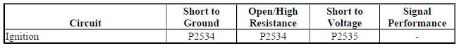
DTC P2534
Ignition On/Start Switch Circuit Low Voltage
DTC P2525
Ignition On/Start Switch Circuit High Voltage
Diagnostic Fault Information
Circuit/System Description
The chassis control module monitors the ignition voltage circuit in order to determine if the voltage is within the normal operating range.
Conditions for Running the DTC
The engine is running.
Conditions for Setting the DTC
The chassis control module detects that the ignition voltage is less than 6.0 V.
Action Taken When the DTC Sets
DTC P2534 and P2535 are Type A DTCs.
Conditions for Clearing the DTC
DTC P2534 and P2535 are Type A DTCs.
Reference Information
Schematic Reference
Engine Controls Schematics (Encore) , Engine Controls Schematics (Trax)
Connector End View Reference
WIRING SYSTEMS AND POWER MANAGEMENT - COMPONENT CONNECTOR END VIEWS - INDEX - ENCORE WIRING SYSTEMS AND POWER MANAGEMENT - COMPONENT CONNECTOR END VIEWS - INDEX - TRAX
Description and Operation
Fuel System Description (LUJ) , Fuel System Description (LUV)
Electrical Information Reference
- Circuit Testing
- Connector Repairs
- Testing for Intermittent Conditions and Poor Connections
- Wiring Repairs
DTC Type Reference
Powertrain Diagnostic Trouble Code (DTC) Type Definitions (LUV) , Powertrain Diagnostic Trouble Code (DTC) Type Definitions (2H0)
Scan Tool Reference
Control Module References for scan tool information
Circuit/System Testing
- Ignition ON.
- Verify DTC P0562 is not set.
- If the DTC is set
Refer to Diagnostic Trouble Code (DTC) List - Vehicle .
- If the DTC is not set
- Ignition OFF, disconnect the harness connector at the K38 Chassis Control Module, ignition ON.
- Verify a test lamp illuminates between the ignition circuit terminal 21 and ground.
- If the test lamp does not illuminate and the circuit fuse is good
- Ignition OFF.
- Test for less than 2 ohms in the ignition circuit end to end.
- If 2 ohms or greater, repair the open/high resistance in the circuit.
- If less than 2 ohms, verify the fuse is not open and there is voltage at the fuse.
- If the test lamp does not illuminate and the circuit fuse is open
- Ignition OFF.
- Test for infinite resistance between the ignition circuit and ground.
- If less than infinite resistance, repair the short to ground on the circuit.
- If infinite resistance, replace the K38 Chassis Control Module.
- If the test lamp illuminates
- Replace the K38 Chassis Control Module.
Repair Instructions
Perform the Diagnostic Repair Verification after completing the repair .
Control Module References for chassis control module replacement, programming and setup.
DTC P2544
Diagnostic Instructions
- Perform the Diagnostic System Check - Vehicle prior to using this diagnostic procedure.
- Review Strategy Based Diagnosis for a overview of the diagnostic approach.
- Diagnostic Procedure Instructions provides an overview of each diagnostic category.
DTC Descriptors
DTC P2544
Transmission Torque Request Signal Message Counter Incorrect
Circuit/System Description
To improve shift feel, the transmission control module (TCM) is constantly sending the engine control module (ECM) serial data messages with requests to modify engine speed or torque. These serial data messages are sent through two circuits which are part of a communication network called the controller area network (CAN). The ECM sets DTC P2544 when it detects a discrepancy in the structure of the message causing the integrity of the message to be questioned.
Conditions for Running the DTC
- The engine run time is greater than 0.5 s.
- No other CAN errors are present
Conditions for Setting the DTC
The ECM detects that the engine speed and torque modification messages from the TCM are either corrupted or intermittently missing for greater than 4 s.
Action Taken When the DTC Sets
- DTC P2544 is a Type B DTC.
- The TCM commands maximum line pressure during shifts, which results in harsh shifts.
- The TCM freezes adaptive functions.
Conditions for Clearing the DTC
DTC P2544 is a Type B DTC.
Diagnostic Aids
An intermittent fault in the CAN circuits will cause the ECM to set DTC P2544.
Reference Information
DTC Type Reference
Powertrain Diagnostic Trouble Code (DTC) Type Definitions (LUV) , Powertrain Diagnostic Trouble Code (DTC) Type Definitions (2H0)
Circuit/System Verification
NOTE:
- DTC P2544 is an informational DTC.
- Diagnose all other engine control module DTCs prior to DTC P2544.
- Verify that no other DTCs are set except for DTC P2544.
- If any other DTCs are set
Refer to Diagnostic Trouble Code (DTC) List - Vehicle .
- If only DTC P2544 is set
- Replace the K71 Transmission Control Module.
- Operate the vehicle within the conditions for running the DTC. You may also operate the vehicle within the conditions that you observed from the freeze frame/failure records data.
- Verify the DTC does not set.
- If DTC sets
Replace the K20 Engine Control Module.
- If DTC does not set
- All OK.
Repair Instructions
Perform the Diagnostic Repair Verification after completing the repair.
Control Module References for ECM or TCM replacement, programming, and setup
