Chevrolet Trax: DTC P0722, P0723, P077C, OR P077D
Diagnostic Instructions
- Perform the Diagnostic System Check - Vehicle prior to using this diagnostic procedure.
- Review Strategy Based Diagnosis for an overview of the diagnostic approach.
- Diagnostic Procedure Instructions provides an overview of each diagnostic category.
DTC Descriptors
DTC P0722
Output Speed Sensor Circuit No Signal
DTC P0723
Output Speed Sensor Circuit Intermittent
DTC P077C
Output Speed Sensor Circuit Low Voltage
DTC P077D
Output Speed Sensor Circuit High Voltage
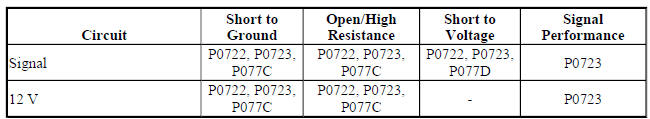
Diagnostic Fault Information
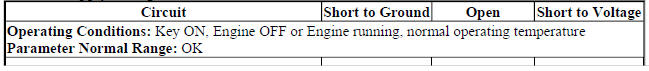
Typical Scan Tool Data
Transmission OSS
.jpg)
ISS/OSS Supply Voltage
.jpg)
Circuit/System Description
The output shaft speed (OSS) sensor is a hall-effect type sensor. The OSS sensor mounts to the automatic transmission case assembly and connects to the control solenoid valve assembly through a 2-wire harness and connector. The sensor faces the park gear teeth. The sensor receives battery voltage on the OSS sensor supply voltage circuit from the transmission control module (TCM). As the output shaft rotates, the sensor produces a signal frequency based on the park gear teeth. This signal is transmitted through the OSS sensor signal circuit to the TCM. The TCM uses the OSS sensor signal to calculate output shaft speed to determine commanded line pressure, transmission shift patterns, vehicle speed and gear ratio.
Conditions for Running the DTC
P0722
- DTC P0101, P0102, P0103, P0121, P0122, P0123, P0716, P0717, P0722, or P0723 is not set.
- Ignition voltage is 9-32 V.
- Engine speed is 400-7,500 RPM for 5 s.
- Engine torque signal is valid.
- Throttle position signal is valid.
- Transmission input speed is between 1,000-8,191 RPM.
- Calculated throttle position is 8% or greater.
- Engine torque is 30 N.m (22 lb ft) or greater.
- Transmission fluid temperature is -40ºC (-40ºF) or greater.
- DTC runs continuously when the above conditions are met.
P0723
- DTC P0101, P0102, P0103, P0121, P0122, P0123, P0723, P0973, P0974, P0976, or P0977 is not set.
- Ignition voltage is 9-32 V.
- Greater than 5 s since last transmission upshift or downshift.
- Engine speed is 400-7,500 RPM for 5 s.
- DTC runs continuously when the above conditions are met.
P077C
- DTC P077D is not set.
- Ignition voltage is 9-32 V.
- DTC runs continuously when the above conditions are met.
P077D
- DTC P077C is not set.
- Ignition voltage is 9-32 V.
- DTC runs continuously when the above conditions are met.
Conditions for Setting the DTC
P0722
Transmission output speed is 35 RPM or less for 5 s.
P0723
- Transmission output speed is 105 RPM or greater.
- TCM detects the transmission output shaft speed dropped greater than 1,000 RPM for 3 s.
P077C
Transmission OSS sensor analog signal voltage is 0.25 V or less for 4 s.
P077D
Transmission OSS sensor analog signal voltage is 4.75 V or greater for 4 s.
Action Taken When the DTC Sets
P0722
- P0722 is a Type A DTC.
- TCM freezes transmission adaptive functions.
- TCM commands maximum line pressure.
- TCM forces the torque converter clutch (TCC) OFF.
- TCM Enables torque management.
- TCM limits the transmission to reverse and 2nd gear.
- TCM inhibits neutral idle.
- TCM inhibits auto grade braking.
- TCM inhibits Tap-Up/Tap-Down functions.
- TCM inhibits manual up, manual down shifts with the shift selector.
- TCM commands 2nd gear when in a forward range and the output speed is less than 700 RPM, or neutral if the output speed is 700 RPM or greater.
P0723, P077C or P077D
- P0723, P077C, and P077D are Type A DTCs.
- TCM freezes transmission adaptive functions.
- TCM forces TCC OFF.
- TCM commands the high side driver OFF.
- TCM commands maximum line pressure.
- TCM enables torque management.
- TCM limits the transmission to reverse and 4th gear.
- TCM inhibits neutral idle.
- TCM inhibits Tap-Up/Tap-Down functions.
- TCM inhibits manual up, manual down shifts with the shift selector.
- TCM inhibits auto grade braking.
Conditions for Clearing the DIC/DTC
P0722, P0723, P077C, and P077D are Type A DTCs.
Diagnostic Aids
- Inspect the OSS senor, harness, and connector for metallic debris.
- Proper torque of the OSS sensor mounting bolt is critical to proper OSS sensor operation.
- If the scan tool ISS/OSS Supply Voltage indicates out of range, the fault could also be caused by the transmission input shaft speed sensor.
Reference Information
Schematic Reference
Automatic Transmission Controls Schematics (Encore, MH8 or MHB) , Automatic Transmission Controls Schematics (Trax, MH8 or MHB)
Connector End View Reference
WIRING SYSTEMS AND POWER MANAGEMENT - COMPONENT CONNECTOR END VIEWS - INDEX - ENCORE WIRING SYSTEMS AND POWER MANAGEMENT - COMPONENT CONNECTOR END VIEWS - INDEX - TRAX
- Inline Harness Connector End Views (Encore) , Inline Harness Connector End Views (Trax)
Description and Operation
- Electronic Component Description
- Transmission Component and System Description
- Transmission General Description
Electrical Information Reference
- Circuit Testing
- Connector Repairs
- Testing for Intermittent Conditions and Poor Connections
- Wiring Repairs
DTC Type Reference
Powertrain Diagnostic Trouble Code (DTC) Type Definitions (LUV) , Powertrain Diagnostic Trouble Code (DTC) Type Definitions (2H0)
Scan Tool Reference
Control Module References for scan tool information
Special Tools
DT-48616-10 Adapter Harness
For equivalent regional tools, refer to Special Tools .
Circuit/System Verification
- Ignition ON.
- Verify the scan tool ISS/OSS Supply Voltage parameter displays OK.
If OK is not displayed
Refer to Circuit/System Testing.
If OK is displayed
- Verify the scan tool Transmission OSS parameter changes with vehicle speed or does not drop out, while operating the vehicle at 16-32 km/h (10-20 mph).
If the Transmission OSS does not vary with vehicle speed or drops out
Refer to Circuit/System Testing
If the Transmission OSS varies with vehicle speed and does not drop out
- Operate the vehicle within the Conditions for Running the DTC. You may also operate the vehicle within the conditions that you observed from the Freeze Frame/Failure Records data.
- Verify the DTC does not set.
If the DTC sets
Refer to Circuit/System Testing.
If the DTC does not set
- All OK.
Circuit/System Testing
NOTE: You must perform the Circuit/System Verification first.
- Ignition OFF, remove the Q8 Control Solenoid Valve Assembly.
- Connect the DT-48616-10 adapter harness between the vehicle harness connector and the Q8 Control Solenoid Valve Assembly connector.
- Ignition ON.
- Test for 11-13 V between the OSS sensor voltage circuit terminal B at the Q8 Control Solenoid Valve Assembly X4 connector and ground.
If not between 11-13 V
Replace the Q8 Control Solenoid Valve Assembly.
If between 11-13 V
- Verify the scan tool Transmission OSS parameter is between 745-825 RPM when performing the output shaft speed test. Refer to Control Solenoid Valve and Transmission Control Module Assembly Input Shaft Speed/Output Shaft Speed Input Test.
If not between 745-825 RPM
Replace the Q8 Control Solenoid Valve Assembly.
If between 745-825 RPM
- Verify there is no damage to the park gear, or misalignment between the B14A Transmission Output Shaft Speed Sensor and the park gear.
If the park gear is damaged or misaligned
Repair or replace as necessary.
If the park gear is not damaged or misaligned
- Replace the B14A Transmission Output Shaft Speed Sensor.
Repair Instructions
Perform the Diagnostic Repair Verification after completing the repair.
- Perform the Transmission Adaptive Values Learn following all transmission repairs
- Input and Output Speed Sensor Installation
- Input and Output Speed Sensor Removal
- Control Module References - for Control Solenoid Valve Assembly replacement, programming and setup
