Chevrolet Trax: DTC P0097, P0098, OR P0099
Diagnostic Instructions
- Perform the Diagnostic System Check - Vehicle prior to using this diagnostic procedure.
- Review Strategy Based Diagnosis for an overview of the diagnostic approach.
- Diagnostic Procedure Instructions provides an overview of each diagnostic category.
DTC Descriptors
DTC P0097
Intake Air Temperature (IAT) Sensor 2 Circuit Low Voltage
DTC P0098
Intake Air Temperature (IAT) Sensor 2 Circuit High Voltage
DTC P0099
Intake Air Temperature (IAT) Sensor 2 Circuit Intermittent
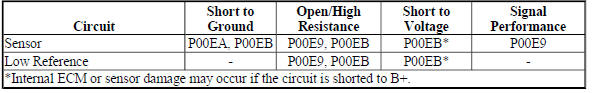
Diagnostic Fault Information
IAT Sensor 2
.jpg)
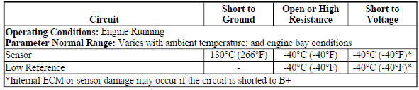
Typical Scan Tool Data
IAT Sensor 2
.jpg)
.jpg)
Circuit/System Description
The sensors listed below are integrated within the multifunction intake air sensor:
- Intake Air Temperature (IAT) sensor 1
- IAT sensor 2
- Humidity sensor
- Mass Air Flow (MAF) sensor
- Barometric (BARO) pressure sensor
The IAT sensor 2 and the humidity sensor share the same circuit. The IAT sensor 2 signal is displayed by the scan tool as Hertz (Hz) and ºC (ºF).
The sensors listed below share an ECM supplied 5 V reference circuit:
- IAT sensor 2
- Humidity sensor
- Barometric pressure (BARO) sensor
The sensors listed below share an ECM supplied low reference circuit:
- IAT sensor 1
- IAT sensor 2
- Humidity sensor
- Barometric pressure (BARO) sensor
IAT Sensor 2 - Temperature, Frequency Table
.jpg)
Conditions for Running the DTCs
P0097, P0098, and P0099
- The ignition is ON, or the engine is running.
- The Ignition voltage is at least 11 V.
- The DTCs run continuously within the enabling conditions.
Conditions for Setting the DTCs
NOTE: The scan tool display range is between -40 and +150ºC (-40 and +302ºF).
P0097
The ECM detects that the IAT sensor 2 signal is less than 10 Hz, colder than -60ºC (-76ºF), for greater than 5 s.
P0098
The ECM detects that the IAT sensor 2 signal is greater than 390 Hz, warmer than 150ºC (302ºF), for greater than 5 s.
P0099
The ECM detects that the IAT sensor 2 signal is intermittent or has abruptly changed for longer than 5 s.
Action Taken When the DTC Sets
- DTCs P0097, P0098, and P0099 are Type B DTCs.
- The ECM commands the cooling fans ON.
Conditions for Clearing the MIL/DTCs
DTCs P0097, P0098, and P0099 are Type B DTCs.
Diagnostic Aids
- With the ignition ON, when the engine is cold and not running, properly functioning IAT sensor 2 will gradually increase the scan tool IAT Sensor 2 parameters. This is due to the heat that is generated by the multifunction intake air sensor heating elements.
- The humidity sensor and the IAT sensor 2 signals are sent to the ECM on the same circuit. If the IAT Sensor 2 parameter displays the values: 10 Hz; -40ºC (-40ºF), and there are also Humidity Sensor DTCs, check for a circuit problem.
Reference Information
Schematic Reference
Engine Controls Schematics (Encore) , Engine Controls Schematics (Trax)
Connector End View Reference
WIRING SYSTEMS AND POWER MANAGEMENT - COMPONENT CONNECTOR END VIEWS - INDEX - ENCORE WIRING SYSTEMS AND POWER MANAGEMENT - COMPONENT CONNECTOR END VIEWS - INDEX - TRAX
Electrical Information Reference
- Circuit Testing
- Connector Repairs
- Testing for Intermittent Conditions and Poor Connections
- Wiring Repairs
Powertrain Component Views
Powertrain Component Views
DTC Type Reference
Powertrain Diagnostic Trouble Code (DTC) Type Definitions (LUV) , Powertrain Diagnostic Trouble Code (DTC) Type Definitions (2H0)
Scan Tool Reference
Control Module References Control Module References for scan tool information
Special Tools
EL-38522-A Variable Signal Generator
For equivalent regional tools, refer to Special Tools (Diagnostic Tools) .
Circuit/System Verification
- Ignition ON.
- Verify that DTC DTC P0641, P0651, P0697, or P06A3 is not set.
If any of the DTCs are set
Refer to DTC P0641, P0651, P0697, or P06A3 (ECM) for further diagnosis.
- If none of the DTCs are set
NOTE: To minimize the effects of residual engine heat and sensor internal heating elements, perform Steps 3 and 4 of this verification procedure only if the ignition has been OFF for 8 hours or more.
- Ignition ON.
- Verify the following scan tool parameters are within 25ºC (45ºF) of each other.
- Start-Up IAT Sensor 1
- IAT Sensor 2
- IAT Sensor 3; where equipped
If not within 25ºC (45ºF)
Refer to Circuit/System Testing.
If within 25ºC (45ºF)
- Engine idling, verify the following scan tool parameters are between: -38 and +149ºC (-36 and +300ºF).
- IAT Sensor 1
- IAT Sensor 2
- IAT Sensor 3; where equipped
If not between: -38 and +149ºC (-36 and +300ºF)
Refer to Circuit System Testing.
If between: -38 and +149ºC (-36 and +300ºF)
- Operate the vehicle within the conditions for running the DTC. You may also operate the vehicle within the conditions that you observed from the freeze frame/failure records data.
- Verify the DTC does not set.
If the DTC sets
Refer to Circuit/System Testing.
If the DTC does not set
- All OK
Circuit/System Testing
- Ignition OFF, and all vehicle systems OFF, it may take up to 2 min. for all vehicle systems to power down. Disconnect the harness connector at the B75C Multifunction Intake Air sensor.
- Test for less than 2 ohms between the low reference circuit terminal 7 and ground.
If 2 ohms or greater
- Ignition OFF, disconnect the harness connector at the K20 Engine Control Module.
- Test for less than 2 ohms in the low reference circuit end to end.
- If 2 ohms or greater, repair the open or high resistance in the circuit.
- If less than 2 ohms replace the K20 Engine Control Module.
If less than 2 ohms
- Ignition ON, test for 4.8-5.2 V between the 5 V reference circuit terminal 2 and ground.
If less than 4.8 V
- Ignition OFF, disconnect the harness connector at the K20 Engine Control Module.
- Test for infinite resistance between the signal circuit and ground.
- If less than infinite resistance, repair the short to ground on the circuit.
- If infinite resistance
- Test for less than 2 ohms in the signal circuit end to end.
- If 2 ohms or greater, repair the open/high resistance in the circuit.
- If less than 2 ohms, replace the K20 Engine Control Module.
If greater than 5.2 V
NOTE: If the 5 V reference circuit is shorted to a voltage the engine control module or the sensor may be damaged.
- Ignition OFF, disconnect the harness connector at the K20 Engine Control Module.
- Ignition ON, test for less than 1 V between the 5 V reference circuit and ground.
- If 1 V or greater, repair the short to voltage on the circuit.
- If less than 1 V, replace the K20 Engine Control Module.
If between 4.8-5.2 V
- Ignition ON, test for 4.8-5.2 V between the signal circuit terminal 1 and ground.
If less than 4.8 V
- Ignition OFF, disconnect the harness connector at the K20 Engine Control Module.
- Test for infinite resistance between the signal circuit and ground.
- If less than infinite resistance, repair the short to ground on the circuit.
- If infinite resistance
- Test for less than 2 ohms in the signal circuit end to end.
- If 2 ohms or greater, repair the open/high resistance in the circuit.
- If less than 2 ohms, replace the K20 Engine Control Module.
If greater than 5.2 V
NOTE: If the signal circuit is shorted to a voltage the engine control module or the sensor may be damaged.
- Ignition OFF, disconnect the harness connector at the K20 Engine Control Module.
- Ignition ON, test for less than 1 V between the signal circuit and ground.
- If 1 V or greater, repair the short to voltage on the circuit.
- If less than 1 V, replace the K20 Engine Control Module.
If between 4.8-5.2 V
- Determine if EL-38522-A Variable Signal Generator or equivalent is available.
EL-38522-A, Variable Signal Generator; or equivalent is not available
- Replace the K20 Engine Control Module.
- Operate the vehicle within the Conditions for Running the DTC. You may also operate the vehicle within the conditions that you observed from the freeze frame/failure records data.
- Verify the DTC does not set.
If the DTC sets
Refer to step 9.
If the DTC does not set
- All OK.
EL-38522-A, Variable Signal Generator; or equivalent is available
- Ignition OFF, connect the leads of the EL-38522-A Variable Signal Generator as follows:
- Red lead to the signal circuit terminal 1 at the harness connector
- Black leads to ground
- Battery voltage supply lead to B+
- Set the EL-38522-A Variable Signal Generator to the following specifications.
- Signal switch to 5 V
- Duty Cycle switch to 50 % (Normal)
- Frequency switch to 30 Hz
- Ignition ON, verify the scan tool IAT Sensor 2 parameter is between 28-32 Hz.
If not between 28-32 Hz
Replace the K20 Engine Control Module.
If between 28-32 Hz
- Test or replace the B75C Multifunction Intake Air sensor.
Component Testing
Multifunction Intake Air Sensor
- Test the IAT Sensor 2 by varying the sensor temperature while monitoring the air temperature with a thermometer. Compare the readings with the scan tool IAT Sensor 2 parameter. The values should be within 5%.
If not within 5%
Replace the B75C Multifunction Intake Air sensor.
If within 5%
- All OK.
Repair Instructions
Perform the Diagnostic Repair Verification after completing the repair.
- Mass Airflow Sensor Replacement for multifunction intake air sensor replacement.
- Control Module References for Engine Control Module replacement, programming, and setup.
DTC P00C7
Diagnostic Instructions
- Perform the Diagnostic System Check - Vehicle prior to using this diagnostic procedure.
- Review Strategy Based Diagnosis for an overview of the diagnostic approach.
- Diagnostic Procedure Instructions provides an overview of each diagnostic category.
DTC Descriptor
DTC P00C7
Intake Air Pressure Measurement System - Multiple Sensors Not Plausible
Circuit/System Description
The Intake Air Pressure Measurement System consists of 3 sensors:
- The barometric pressure (BARO) is measured by the B75C Multifunction Intake Air Sensor
- The manifold absolute pressure (MAP) is measured by the B74 Manifold Absolute Pressure Sensor
- The boost pressure is measured by the B111B Turbocharger Boost/Intake Air Temperature Sensor
Conditions for Running the DTC
- DTCs P0106, P0107, P0108, P2122, P2123, P2127, P2128, P2138 or P2610 are not set.
- The engine is running.
- Time between current ignition cycle and the last time the engine was running is greater than 10 s.
- Manifold pressure between 50 and 115 kPa (7.25 and 16.68 PSI).
- BARO pressure between 50 and 115 kPa (7.25 and 16.68 PSI).
- Turbocharger boost pressure between 50 and 115 kPa (7.25 and 16.68 PSI).
- This DTC runs continuously within the enabling conditions.
Conditions for Setting the DTC
The ECM detects an inconsistency between pressure sensors in the induction system in which a particular sensor cannot be identified as the failed sensor. The difference is greater than 10 kPa (1.5 PSI).
Action Taken When the DTC Sets
DTC P00C7 is a Type B DTC.
Conditions for Clearing the DTC
DTC P00C7 is a Type B DTC.
Reference Information
Schematic Reference
Engine Controls Schematics (Encore) , Engine Controls Schematics (Trax)
Connector End View Reference
WIRING SYSTEMS AND POWER MANAGEMENT - COMPONENT CONNECTOR END VIEWS - INDEX - ENCORE WIRING SYSTEMS AND POWER MANAGEMENT - COMPONENT CONNECTOR END VIEWS - INDEX - TRAX
Electrical Information Reference
- Circuit Testing
- Connector Repairs
- Testing for Intermittent Conditions and Poor Connections
- Wiring Repairs
DTC Type Reference
Powertrain Diagnostic Trouble Code (DTC) Type Definitions (LUV) , Powertrain Diagnostic Trouble Code (DTC) Type Definitions (2H0)
Scan Tool Reference
Control Module References for scan tool information
Circuit/System Verification
- Ignition ON.
- Verify that DTCs P0106, P0107, P0236, P0237, P0238, P2227, P2228, P2229, or P2230, are not set.
- If any of the DTCs are set
Refer to Diagnostic Trouble Code (DTC) List - Vehicle for further diagnosis.
- If none of the DTCs is set
- Verify none of the following conditions exist:
- The air intake duct system for loose connecting clamps, cracks, or other damage
- A damaged Q38 Throttle Body blade or shaft
- Splits, kinks, or improper connections at the vacuum hoses
- Faulty positive crankcase ventilation system operation
- Carbon deposits on the throttle blade.
- Vacuum leaks at the intake manifold, Q38 Throttle Body, Q17 Fuel Injector O-rings, and B111
- Intake Manifold Pressure and Air Temperature Sensor.
If a condition exist
Repair as necessary.
- Ignition ON.
- Verify the following scan tool parameters are within range of the
Altitude vs. Barometric Pressure table.
Refer to: Altitude Versus Barometric Pressure table.
- BARO Sensor
- MAP Sensor
- Turbocharger Boost Sensor
If a sensor parameter is not within range
Refer to the appropriate diagnostic below for further diagnosis.
- Barometric Pressure (BARO) Sensor. Refer to: DTC P2227-P2230
- Manifold Absolute Pressure (MAP) Sensor. Refer to: DTC P0106
- Turbocharger Boost Pressure Sensor. Refer to: DTC P0236
If all sensor parameters are within range
- All OK
Repair Instructions
Perform the Diagnostic Repair Verification after completing the repair.
Control Module References for Engine Control Module replacement, programming and setup.
DTC P00E9
Diagnostic Instructions
- Perform the Diagnostic System Check - Vehicle prior to using this diagnostic procedure.
- Review Strategy Based Diagnosis for an overview of the diagnostic approach.
- Diagnostic Procedure Instructions provides an overview of each diagnostic category.
DTC Descriptor
DTC P00E9
Intake Air Temperature (IAT) Sensor 3 Circuit Performance
Diagnostic Fault Information
IAT Sensor 3
Typical Scan Tool Data
IAT Sensor 3
Circuit/System Description
The intake air temperature (IAT) sensor 3 is a variable resistor that changes an engine control module (ECM) supplied 5 V signal. The signal varies with inlet air temperature and is displayed by the scan tool as ºC (ºF).
The IAT sensor 3 is integrated with the B111B Turbocharger Boost/Intake Air Temperature Sensor in the sensor bore, which is located before the throttle body. The ECM supplies a ground for the IAT sensor 3 low reference circuit.
The IAT sensor 1 and IAT sensor 2 are part of the B75C Multifunction Intake Air Sensor. The IAT sensor 1 produces an analog signal on pin-8 of the sensor. The IAT sensor 2 produces a frequency modulated signal on pin-1 of the sensor.
IAT Sensor 3 - Temperature, Resistance, Voltage Table
.jpg)
Conditions for Running the DTC
P00E9
- DTCs P0097, P0098, P00EA, P00EB, P0111, P0112, P0113, P0117, P0118, or P1682 are not set.
- The vehicle has been OFF at least 8 hours.
- Ignition voltage is at least 11 V.
- This DTC runs once per ignition cycle when the enabling conditions are met.
Conditions for Setting the DTC
NOTE: P00E9 Can fail under any of the following 3 sets of conditions
P00E9-Condition 1
- The ECM determines the absolute difference between IAT sensor 1 start-up temperature and the IAT sensor 2 start-up temperature is less or equal to 25ºC (45ºF).
AND
- The ECM determines the absolute difference between IAT sensor 3 start-up temperature and the IAT sensor 1 start-up temperature is greater than 25ºC (45ºF).
AND
- The ECM determines the absolute difference between IAT sensor 3 start-up temperature and the IAT sensor 2 start-up temperature is greater than 25ºC (45ºF).
P00E9-Condition 2
- The ECM determines the IAT sensor 1 start-up temperature is between the IAT sensor 3 and the IAT sensor 2 start-up temperatures
AND
- The ECM determines the absolute difference between IAT sensor 3 start-up temperature and the IAT sensor 2 start-up temperature is greater than 25ºC (45ºF).
AND
- The ECM determines the absolute difference between IAT sensor 3 and the IAT sensor 1 start-up temperatures is greater than the absolute difference between IAT sensor 2 and the IAT sensor 1 start-up temperatures.
P00E9-Condition 3
- The ECM determines the IAT sensor 2 start-up temperature is between the IAT sensor 3 and the IAT sensor 1 start-up temperatures
AND
- The ECM determines the absolute difference between IAT sensor 3 and the IAT sensor 1 start-up temperatures is greater than 25ºC (45ºF).
AND
- The absolute difference between IAT sensor 3 and the IAT sensor 2 start-up temperatures is greater than the absolute difference between IAT sensor 2 and the IAT sensor 1 start-up temperatures.
DTC P00E9 runs once an ignition cycle when one of the above 3 enabling sets of conditions are met.
Action Taken When the DTC Sets
- DTC P00E9 is Type C DTC, MY14 and newer vehicles.
- DTC P00E9 is Type B DTC, MY13 and older vehicles
Conditions for Clearing the DTCs
- DTC P00E9 is Type C DTC, MY14 and newer vehicles.
- DTC P00E9 is Type B DTC, MY13 and older vehicles.
Reference Information
Schematic Reference
Engine Controls Schematics (Encore) , Engine Controls Schematics (Trax)
Connector End View Reference
WIRING SYSTEMS AND POWER MANAGEMENT - COMPONENT CONNECTOR END VIEWS - INDEX - ENCORE WIRING SYSTEMS AND POWER MANAGEMENT - COMPONENT CONNECTOR END VIEWS - INDEX - TRAX
Electrical Information Reference
- Circuit Testing
- Connector Repairs
- Testing for Intermittent Conditions and Poor Connections
- Wiring Repairs
Powertrain Component Views
Powertrain Component Views
DTC Type Reference
Powertrain Diagnostic Trouble Code (DTC) Type Definitions (LUV) , Powertrain Diagnostic Trouble Code (DTC) Type Definitions (2H0)
Scan Tool Reference
Control Module References for scan tool information
Special Tools
EL-38522-A Variable Signal Generator
For equivalent regional tools, refer to Special Tools (Diagnostic Tools) .
Circuit/System Verification
- Ignition ON.
- Verify that DTC DTC P0641, P0651, P0697, or P06A3 is not set.
If any of the DTCs are set
Refer to DTC P0641, P0651, P0697, or P06A3 (ECM) for further diagnosis.
If none of the DTCs are set
NOTE: To minimize the effects of residual engine heat and sensor internal heating elements, perform Steps 3 and 4 of this verification procedure only if the ignition has been OFF for 8 hours or more.
- Ignition ON.
- Verify the following scan tool parameters are within 25ºC (45ºF) of each other.
- Start-Up IAT Sensor 1
- IAT Sensor 2
- IAT Sensor 3
If not within 25ºC (45ºF)
Refer to Circuit/System Testing.
If within 25ºC (45ºF)
- Engine idling, verify the IAT Sensor 3 scan tool parameter is between: -38 and +128ºC (-36 and +262ºF).
If not between: -38 and +128ºC (-36 and +262ºF)
Refer to Circuit System Testing.
If between: -38 and +128ºC (-36 and +262ºF)
- Operate the vehicle within the Conditions for Running the DTC. You may also operate the vehicle within the conditions that you observed from the Freeze Frame/Failure Records data.
- Verify the DTC does not set.
If the DTC sets
Refer to Circuit/System Testing.
If the DTC does not set
- All OK
Circuit/System Testing
NOTE: You must perform the Circuit/System Verification before proceeding with Circuit/System Testing.
- Check the integrity of the entire air induction system and verify that none of the following conditions exist:
- A loose or disconnected charge air cooler hose or pipe
- A blocked or obstructed charge air cooler, including: after-market grill covers
- Any snow or ice build-up at the charge air cooler in cold climates
- Any mud or dirt build-up at the charge air cooler
- A restricted or collapsed air intake duct
- An intake manifold leak
- A MAP sensor seal that is leaking, missing, or damaged
- A misaligned or damaged air intake duct
- Any water intrusion in the induction system
- An Intake Manifold Resonator with a leaking seal, or a cracked or broken housing
If a condition exists
Repair or replace component as appropriate.
If no condition exists
- Ignition OFF, and all vehicle systems OFF, it may take up to 2 min. for all vehicle systems to power down. Disconnect the harness connector at the B111B Turbocharger Boost/Intake Air Temperature sensor.
- Test for less than 2 ohms between the low reference circuit terminal 1 and ground.
If 2 ohms or greater
- Ignition OFF, disconnect the harness connector at the K20 Engine Control Module.
- Test for less than 2 ohms in the low reference circuit end to end.
- If 2 ohms or greater, repair the open or high resistance in the circuit.
- If less than 2 ohms replace the K20 Engine Control Module.
If less than 2 ohms
- Ignition ON, test for 4.8-5.2 V between the signal circuit terminal 2 and ground.
If less than 4.8 V
- Ignition OFF, disconnect the harness connector at the K20 Engine Control Module.
- Test for infinite resistance between the signal circuit and ground.
If less than infinite resistance, repair the short to ground on the circuit.
If infinite resistance
- Test for less than 2 ohms in the signal circuit end to end.
- If 2 ohms or greater, repair the open/high resistance in the circuit.
- If less than 2 ohms, replace the K20 Engine Control Module.
If greater than 5.2 V
NOTE: If the signal circuit is shorted to a voltage the engine control module or the sensor may be damaged.
- Ignition OFF, disconnect the harness connector at the K20 Engine Control Module.
- Ignition ON, test for less than 1 V between the signal circuit and ground.
- If 1 V or greater, repair the short to voltage on the circuit.
- If less than 1 V, replace the K20 Engine Control Module.
If between 4.8-5.2 V
- Ignition ON, verify the scan tool IAT Sensor 3 parameter is colder than -39ºC (-38ºF).
If warmer than -39ºC (-38ºF).
- Ignition OFF, disconnect the harness connector at the K20 Engine Control Module.
- Test for infinite resistance between the signal circuit terminal 2 and ground.
- If less than infinite resistance, repair the short to ground on the circuit.
- If infinite resistance
- Test for less than 2 ohms in the signal circuit end to end.
- If 2 ohms or greater, repair the open/high resistance in the circuit.
- If less than 2 ohms, replace the K20 Engine Control Module.
If colder than -39ºC (-38ºF).
- Ignition OFF, install a 3 A fused jumper wire between the signal circuit terminal 2 and the low reference circuit terminal 1.
- Verify the scan tool IAT Sensor 3 parameter is warmer than 128ºC (262ºF).
If colder than 128ºC (262ºF).
- Ignition OFF, remove the jumper wire, disconnect the harness connector at the K20 ECM, ignition ON.
- Test for less than 1 V between the signal circuit and ground.
- If 1 V or greater, repair the short to voltage on the circuit.
- If less than 1 V
- Ignition OFF.
- Test for less than 2 ohms in the signal circuit end to end.
- If 2 ohms or greater, repair the open/high resistance in the circuit.
- If less than 2 ohms, replace the K20 ECM.
If warmer than 128ºC (262ºF).
- Test or replace the B111B Turbocharger Boost/Intake Air Temperature sensor.
Component Testing
Turbocharger Boost/Intake Air Temperature sensor
- Ignition OFF, disconnect the harness connector at the B111B Turbocharger Boost/Intake Air Temperature sensor.
NOTE: A thermometer can be used to test the sensor off the vehicle.
- Test the IAT sensor 3 by varying the sensor temperature while monitoring the sensor resistance. Compare the readings with the Temperature Versus Resistance - Intake Air Temperature Sensor (Bosch Sensor) , Temperature Versus Resistance - Intake Air Temperature Sensor (Delco Sensor) table for the appropriate sensor. The resistance values should be in range of the table values.
If not within the specified range.
Replace the B111B Turbocharger Boost/Intake Air Temperature sensor.
If within the specified range.
- All OK
Repair Instructions
Perform the Diagnostic Repair Verification after completing the repair.
- Intake Air Pressure and Temperature Sensor Replacement for turbocharger boost/intake air temperature sensor replacement
- Mass Airflow Sensor Replacement for multifunction intake air sensor replacement
- Control Module References for Engine Control Module replacement, programming, and setup.
