Chevrolet Trax: DTC P0101
Diagnostic Instructions
- Perform the Diagnostic System Check - Vehicle prior to using this diagnostic procedure.
- Review Strategy Based Diagnosis for an overview of the diagnostic approach.
- Diagnostic Procedure Instructions provides an overview of each diagnostic category.
DTC Descriptor
DTC P0101
Mass Air Flow (MAF) Sensor Performance
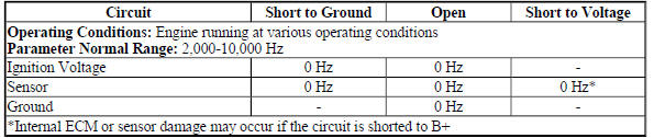
Diagnostic Fault Information
MAF Sensor
.jpg)
.jpg)
Typical Scan Tool Data
MAF Sensor
Circuit Description
The sensors listed below are integrated within the multifunction intake air sensor:
- Intake Air Temperature (IAT) sensor 1
- IAT sensor 2
- Humidity sensor
- Mass Air Flow (MAF) sensor
- Barometric (BARO) pressure sensor
The MAF sensor is an air flow meter that measures the amount of air flowing in the sensor bore. The engine control module (ECM) uses the MAF sensor signal to provide the correct fuel delivery for all engine speeds and loads. A small quantity of air entering the engine indicates a deceleration or idle condition. A large quantity of air entering the engine indicates an acceleration or high load condition.
The ECM applies 5 V to the MAF sensor signal circuit. The sensor produces a variable frequency signal based on the inlet air flow through the sensor bore. The signal varies with engine load and is displayed by the scan tool as Hertz (Hz) and grams per second (g/s). Vehicle ignition voltage and ground circuits are also supplied to the MAF sensor.
The intake flow rationality diagnostic provides the within-range rationality check for the mass air flow (MAF), manifold absolute pressure (MAP), and the throttle position sensors. This is an explicit model-based diagnostic containing 4 separate models for the intake system.
The estimates of MAF and MAP obtained from this system of models and calculations are then compared to the actual measured values from the MAF, MAP, and the throttle position sensors and to each other to determine the appropriate DTC to fail.
The sensors listed below share an ECM supplied 5 V reference circuit:
- IAT sensor 2
- Humidity sensor
- Barometric pressure (BARO) sensor
The sensors listed below share an ECM supplied low reference circuit:
- IAT sensor 1
- IAT sensor 2
- Humidity sensor
- Barometric pressure (BARO) sensor
Conditions for Running the DTCs
- DTCs P0096, P0097, P0098, P0102, P0103, P0107, P0111, P0112, P0113, P0116, P0117, P0118, P0119, P0237, P0238, P0335, P0336, P2227, P2228, P2229, or P2230 are not set.
- The engine speed is between 400-6,000 RPM.
- The engine coolant temperature (ECT) is between -7 and +125ºC (+19 and +257ºF).
- The intake air temperature (IAT) is between -20 and +100ºC (-4 and +212ºF).
- The DTC runs continuously when the above conditions are met.
Conditions for Setting the DTC
The engine control module (ECM) detects that the actual measured airflow from the MAF, MAP, and throttle position sensors is not within range of the calculated airflow that is derived from the system of models for greater than 2 s.
Action Taken When the DTC Sets
DTC P0101 is a Type B DTC.
Conditions for Clearing the MIL/DTC
DTC P0101 is a Type B DTC.
Diagnostic Aids
- Certain aftermarket air filters may cause this DTC to set.
- Certain aftermarket air induction systems may cause this DTC to set.
- Modifications to the air induction system may cause this DTC to set.
Reference Information
Schematic Reference
Engine Controls Schematics (Encore) , Engine Controls Schematics (Trax)
Connector End View Reference
WIRING SYSTEMS AND POWER MANAGEMENT - COMPONENT CONNECTOR END VIEWS - INDEX - ENCORE WIRING SYSTEMS AND POWER MANAGEMENT - COMPONENT CONNECTOR END VIEWS - INDEX - TRAX
Electrical Information Reference
- Circuit Testing
- Connector Repairs
- Testing for Intermittent Conditions and Poor Connections
- Wiring Repairs
Powertrain Component Views
Powertrain Component Views
DTC Type Reference
Powertrain Diagnostic Trouble Code (DTC) Type Definitions (LUV) , Powertrain Diagnostic Trouble Code (DTC) Type Definitions (2H0)
Scan Tool Reference
Control Module References for scan tool information
Special Tools
EL-38522-A Variable Signal Generator
For equivalent regional tools, refer to Special Tools (Diagnostic Tools) .
Circuit/System Verification
- Ignition ON.
- Verify that DTC DTC P0641, P0651, P0697, or P06A3 is not set.
- If any of the DTCs are set
Refer to DTC P0641, P0651, P0697, or P06A3 (ECM) for further diagnosis.
- If none of the DTCs are set
- If you were sent here from DTC P0068, P0106, P0121, P0236, or P1101; refer to Circuit/System Testing.
- Ignition ON.
- Verify the scan tool Throttle Body Idle Airflow Compensation parameter is less than 90 %.
- If 90 % or greater
Refer to Throttle Body Inspection and Cleaning .
- If less than 90 %
- Verify the scan tool Throttle Position Sensors 1 and 2 Agree/Disagree parameter displays Agree while performing the Throttle Sweep Test with a scan tool.
- If Disagree
Refer to DTC P0121-P0123, P0222, P0223, or P2135 for further diagnosis.
- If Agree
- Determine the current vehicle testing altitude.
- Verify the scan tool MAP Sensor pressure parameter is within the range specified in the Altitude Versus Barometric Pressure table.
- If the MAP Sensor parameter is not in range
Refer to DTC P0106 for further diagnosis.
- If the MAP Sensor parameter is within range
- Verify the engine is equipped with a turbocharger.
- If not equipped with a turbocharger
Refer to Step 12.
- If equipped with a turbocharger
- Verify the scan tool Boost Pressure Sensor parameter is within the range specified in the Altitude Versus Barometric Pressure table.
- If the Boost Pressure Sensor parameter is not in range
Refer to DTC P0236 for further diagnosis.
- If the Boost Pressure Sensor parameter is within range
- Verify the scan tool Boost Pressure Sensor parameter decreases after starting the engine.
- If the Boost Pressure Sensor parameter does not decrease
Refer to DTC P0236 for further diagnosis.
- If the Boost Pressure Sensor parameter does decrease
- Engine idling, verify the scan tool MAP Sensor pressure parameter is between 26-52 kPa (3.8-7.5 PSI) and changes with accelerator pedal input.
- If not between 26-52 kPa (3.8-7.5 PSI) or does not change
Refer to DTC P0106 for further diagnosis.
- If between 26-52 kPa (3.8-7.5 PSI) and changes
- Verify the scan tool MAF Sensor g/s parameter changes smoothly and gradually as the engine speed is increased and decreased while performing the actions listed below.
- Engine idling
- Perform the scan tool snapshot function.
- Increase the engine speed slowly to 3,000 RPM and then back to idle.
- Exit from the scan tool snapshot and review the data.
- Observe the MAF Sensor parameter frame by frame with a scan tool.
- If the MAF Sensor parameter does not change smoothly and gradually
Refer to Circuit/System Testing.
- If the MAF Sensor parameter changes smoothly and gradually
- Operate the vehicle within the Conditions for Running the DTC. You may also operate the vehicle within the conditions that you observed from the Freeze Frame/Failure Records data.
- Verify the DTC does not set.
- If the DTC does set
Refer to Circuit/System Testing for further diagnosis.
- If the DTC does not set
- All OK
Circuit/System Testing
NOTE: You must perform the Circuit/System Verification before proceeding with Circuit/System Testing.
- Check the integrity of the entire air induction system by verifying that none of the following conditions exist:
- Any damaged components
- Improper operation of turbocharger wastegate actuator or bypass valve; where equipped
- Improperly installed components
- Collapsed, restricted, or damaged components
- Loose clamps, cracks, or other damage
- An air flow restriction
- Restricted air filter
- Splits, kinks, leaks, or improper connections at the vacuum hoses
- Vacuum leaks at the intake manifold, MAP sensor, and throttle body
- Water intrusion
- Any snow or ice buildup, in cold climates
- Contamination of the Multifunction Intake Air sensor element
If a condition is found
Repair or replace component as appropriate.
If no condition is found
- Ignition OFF, disconnect the harness connector at the B75C Multifunction Intake Air sensor.
- Test for less than 2 ohms between the ground circuit terminal 4 and ground.
If 2 ohms or greater
- Ignition OFF.
- Test for less than 2 ohms in the ground circuit end to end.
- If 2 ohms or greater, repair the open/high resistance in the circuit.
- If less than 2 ohms, repair the open/high resistance in the ground connection.
If less than 2 ohms
- Ignition ON.
- Verify that a test lamp illuminates between the ignition circuit terminal 5 and ground.
If the test lamp does not illuminate and the circuit fuse is good
- Ignition OFF, remove the test lamp and remove the fuse for the ignition circuit.
- Test for less than 2 ohms in the ignition circuit end to end.
- If 2 ohms or greater, repair the open/high resistance in the circuit.
- If less than 2 ohms, verify the fuse is not open and there is voltage at the fuse.
If the test lamp does not illuminate and the circuit fuse is open
- Ignition OFF, remove the test lamp and remove the fuse for the ignition circuit.
- Test for infinite resistance between the ignition circuit and ground.
- If less than infinite resistance, repair the short to ground on the circuit.
- If infinite resistance
- Test for greater than 2 ohms between the ignition circuit terminal 5 and ground
- If less than 2 ohms, repair the short to ground on the circuit.
- If greater than 2 ohms, test all the components connected to the circuit and repair or replace as necessary.
If a test lamp illuminates
- Ignition ON, test for 4.8-5.2 V between the signal circuit terminal 3 and ground.
If less than 4.8 V
- Ignition OFF, disconnect the harness connector at the K20 Engine Control Module.
- Test for infinite resistance between the signal circuit and ground.
- If less than infinite resistance, repair the short to ground on the circuit.
- If infinite resistance
- Test for less than 2 ohms in the signal circuit end to end.
- If 2 ohms or greater, repair the open/high resistance in the circuit.
- If less than 2 ohms, replace the K20 Engine Control Module.
If greater than 5.2 V
- Ignition OFF, disconnect the harness connector at the K20 Engine Control Module.
- Ignition ON, test for less than 1 V between the signal circuit and ground.
- If 1 V or greater, repair the short to voltage on the circuit.
- If less than 1 V, replace the K20 Engine Control Module.
If between 4.8-5.2 V
- Determine if EL-38522-A Variable Signal Generator or equivalent is available.
- EL-38522-A, Variable Signal Generator; or equivalent is not available
- Test or replace the B75C Multifunction Intake Air sensor.
- Operate the vehicle within the Conditions for Running the DTC. You may also operate the vehicle within the conditions that you observed from the freeze frame/failure records data.
- Verify the DTC does not set.
- If the DTC sets
Replace the K20 Engine Control Module.
- If no DTCs set
- All OK.
- EL-38522-A, Variable Signal Generator; or equivalent is available
- Ignition OFF, connect the leads of the EL-38522-A Variable Signal Generator as follows:
- Red lead to the signal circuit terminal 3 at the harness connector
- Black leads to ground
- Battery voltage supply lead to B+
- Set the EL-38522-A Variable Signal Generator to the following specifications.
- Signal switch to 5 V
- Frequency switch to 5 kHz
- Duty Cycle switch to 50 % (Normal)
- Engine idling, verify the scan tool MAF Sensor parameter is between 4,950-5,050 Hz.
- If not between 4,950-5,050 Hz.
Replace the K20 Engine Control Module.
- If between 4,950-5,050 Hz.
- Test or replace the B75C Multifunction Intake Air sensor.
Repair Instructions
Perform the Diagnostic Repair Verification after completing the repair.
- Mass Airflow Sensor Replacement for multifunction intake air sensor replacement.
- Control Module References for Engine Control Module replacement, programming, and setup.
