Chevrolet Trax: DTC P0102 OR P0103
Diagnostic Instructions
- Perform the Diagnostic System Check - Vehicle prior to using this diagnostic procedure.
- Review Strategy Based Diagnosis for an overview of the diagnostic approach.
- Diagnostic Procedure Instructions provides an overview of each diagnostic category.
DTC Descriptors
DTC P0102
Mass Air Flow (MAF) Sensor Circuit Low Frequency
DTC P0103
Mass Air Flow (MAF) Sensor Circuit High Frequency
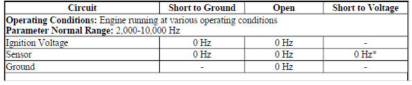
Diagnostic Fault Information
MAF Sensor
.jpg)
Typical Scan Tool Data
MAF Sensor
.jpg)
Circuit Description
The sensors listed below are integrated within the multifunction intake air sensor:
- Intake Air Temperature (IAT) sensor 1
- IAT sensor 2
- Humidity sensor
- Mass Air Flow (MAF) sensor
- Barometric (BARO) pressure sensor
The MAF sensor is an air flow meter that measures the amount of air flowing in the sensor bore. The engine control module (ECM) uses the MAF sensor signal to provide the correct fuel delivery for all engine speeds and loads. A small quantity of air entering the engine indicates a deceleration or idle condition. A large quantity of air entering the engine indicates an acceleration or high load condition.
The ECM applies 5 V to the MAF sensor signal circuit. The sensor produces a variable frequency signal based on the inlet air flow through the sensor bore. The signal varies with engine load and is displayed by the scan tool as Hertz (Hz) and grams per second (g/s). Vehicle ignition voltage and ground circuits are also supplied to the MAF sensor.
The sensors listed below share an ECM supplied 5 V reference circuit:
- IAT sensor 2
- Humidity sensor
- Barometric pressure (BARO) sensor
The sensors listed below share an ECM supplied low reference circuit:
- IAT sensor 1
- IAT sensor 2
- Humidity sensor
- Barometric pressure (BARO) sensor
Conditions for Running the DTCs
- The engine is running for at least 1 s.
- The engine speed is at least 300 RPM.
- The ignition signal is at least 10 V.
- The above conditions are met for at least 1 s.
- The DTC runs continuously when the above conditions are met.
Conditions for Setting the DTCs
P0102
The ECM detects that the MAF Sensor signal parameter is less than 1,837 Hz (about 0.39 g/s) for at least 250 cylinder firing events.
P0103
The ECM detects that the MAF Sensor signal parameter is at least 13,200 Hz (about 810 g/s) for at least 250 cylinder firing events.
Action Taken When the DTCs Set
DTCs P0102 and P0103 are Type B DTCs.
Conditions for Clearing the MIL/DTCs
DTCs P0102 and P0103 are Type B DTCs.
Diagnostic Aids
Verify that any electrical aftermarket devices are properly connected and grounded. Refer to Checking Aftermarket Accessories .
Reference Information
Schematic Reference
Engine Controls Schematics (Encore) , Engine Controls Schematics (Trax)
Connector End View Reference
WIRING SYSTEMS AND POWER MANAGEMENT - COMPONENT CONNECTOR END VIEWS - INDEX - ENCORE WIRING SYSTEMS AND POWER MANAGEMENT - COMPONENT CONNECTOR END VIEWS - INDEX - TRAX
Electrical Information Reference
- Circuit Testing
- Connector Repairs
- Testing for Intermittent Conditions and Poor Connections
- Wiring Repairs
Powertrain Component Views
Powertrain Component Views
DTC Type Reference
Powertrain Diagnostic Trouble Code (DTC) Type Definitions (LUV) , Powertrain Diagnostic Trouble Code (DTC) Type Definitions (2H0)
Scan Tool Reference
Control Module References for scan tool information
Special Tools
EL-38522-A Variable Signal Generator
For equivalent regional tools, refer to Special Tools (Diagnostic Tools) .
Circuit/System Verification
- Engine idling, verify the scan tool MAF Sensor parameter is between 1.75-5.5 g/s.
- If not between 1.75-5.5 g/s
Refer to Circuit/System Testing.
- If between 1.75-5.5 g/s
- Verify the scan tool MAF Sensor g/s parameter changes smoothly and gradually as the engine speed is increased and decreased while performing the actions listed below.
- Engine idling
- Perform the scan tool snapshot function.
- Increase the engine speed slowly to 3,000 RPM and then back to idle.
- Exit from the scan tool snapshot and review the data.
- Observe the MAF Sensor parameter frame by frame with a scan tool.
If the MAF Sensor parameter does not change smoothly and gradually
Refer to Circuit/System Testing.
If the MAF Sensor parameter changes smoothly and gradually
- Operate the vehicle within the Conditions for Running the DTC. You may also operate the vehicle within the conditions that you observed from the Freeze Frame/Failure Records data.
- Verify the DTC does not set.
If the DTC does set
Refer to Circuit/System Testing for further diagnosis.
If the DTC does not set
- All OK
Circuit/System Testing
NOTE: You must perform the Circuit/System Verification before proceeding with Circuit/System Testing.
- Ignition OFF, disconnect the harness connector at the B75C Multifunction Intake Air sensor.
- Test for less than 2 ohms between the ground circuit terminal 4 and ground.
- If 2 ohms or greater
- Ignition OFF. Disconnect the sensor chassis ground.
- Test for less than 2 ohms in the ground circuit end to end.
- If 2 ohms or greater, repair the open/high resistance in the circuit.
- If less than 2 ohms, repair the open/high resistance in the chassis ground connection.
If less than 2 ohms
- Ignition ON.
- Verify that a test lamp illuminates between the ignition circuit terminal 5 and ground.
- If the test lamp does not illuminate and the circuit fuse is good
Ignition OFF, remove the test lamp and remove the fuse for the ignition circuit.
Test for less than 2 ohms in the ignition circuit end to end.
- If 2 ohms or greater, repair the open/high resistance in the circuit.
- If less than 2 ohms, verify the fuse is not open and there is voltage at the fuse.
If the test lamp does not illuminate and the circuit fuse is open
- Ignition OFF, remove the test lamp and remove the fuse for the ignition circuit.
- Test for infinite resistance between the ignition circuit and ground.
- If less than infinite resistance, repair the short to ground on the circuit.
- If infinite resistance
- Test for greater than 2 ohms between the ignition circuit terminal 5 and ground.
- If less than 2 ohms, repair the short to ground on the circuit.
- If greater than 2 ohms, test all the components connected to the circuit and repair or replace as necessary.
If a test lamp illuminates
- Ignition ON, test for 4.8-5.2 V between the signal circuit terminal 3 and ground.
If less than 4.8 V
- Ignition OFF, disconnect the harness connector at the K20 Engine Control Module.
- Test for infinite resistance between the signal circuit and ground.
- If less than infinite resistance, repair the short to ground on the circuit.
- If infinite resistance
- Test for less than 2 ohms in the signal circuit end to end.
- If 2 ohms or greater, repair the open/high resistance in the circuit.
- If less than 2 ohms, replace the K20 Engine Control Module.
- If greater than 5.2 V
- Ignition OFF, disconnect the harness connector at the K20 Engine Control Module.
- Ignition ON, test for less than 1 V between the signal circuit and ground.
- If 1 V or greater, repair the short to voltage on the circuit.
- If less than 1 V, replace the K20 Engine Control Module.
- If between 4.8-5.2 V
- Determine if EL-38522-A Variable Signal Generator or equivalent is available.
- EL-38522-A, Variable Signal Generator; or equivalent is not available
- Test or replace the B75C Multifunction Intake Air sensor.
- Operate the vehicle within the Conditions for Running the DTC. You may also operate the vehicle within the conditions that you observed from the freeze frame/failure records data.
- Verify the DTC does not set.
- If the DTC sets
Replace the K20 Engine Control Module.
- If no DTCs set
- All OK.
- EL-38522-A, Variable Signal Generator; or equivalent is available
- Ignition OFF, connect the leads of the EL-38522-A Variable Signal Generator as follows:
- Red lead to the signal circuit terminal 3 at the harness connector
- Black leads to ground
- Battery voltage supply lead to B+
- Set the EL-38522-A Variable Signal Generator to the following specifications.
- Signal switch to 5 V
- Frequency switch to 5 kHz
- Duty Cycle switch to 50 % (Normal)
- Engine idling, verify the scan tool MAF Sensor parameter is between 4,950-5,050 Hz.
- If not between 4,950-5,050 Hz.
Replace the K20 Engine Control Module.
- If between 4,950-5,050 Hz.
- Test or replace the B75C Multifunction Intake Air sensor.
Repair Instructions
Perform the Diagnostic Repair Verification after completing the repair.
- Mass Airflow Sensor Replacement for multifunction intake air sensor replacement.
- Control Module References for Engine Control Module replacement, programming, and setup.
READ NEXT:
 DTC P0106
Diagnostic Instructions
Perform the Diagnostic System Check - Vehicle prior to using this
diagnostic procedure.
Review Strategy Based Diagnosis for an overview of the diagnostic
approach.
Diag
DTC P0107 OR P0108
Diagnostic Instructions
Perform the Diagnostic System Check - Vehicle prior to using this
diagnostic procedure.
Review Strategy Based Diagnosis for an overview of the diagnostic
approach.
Diag
DTC P0112, P0113, OR P0114
Diagnostic Instructions
Perform the Diagnostic System Check - Vehicle prior to using this
diagnostic procedure.
Review Strategy Based Diagnosis for an overview of the diagnostic
approach.
Diag
SEE MORE:
DTC C0201: Antilock braking system enable relay primary ircuit
Diagnostic Instructions
Perform the Diagnostic System Check - Vehicle prior to using this
diagnostic procedure.
Review Strategy Based Diagnosis for an overview of the diagnostic
approach.
Diagnostic Procedure Instructions provides an overview of each
diagnostic category.
DTC Descriptor
DT
Interior Trim and Paneling - Repair instructions
SPECIFICATIONS
FASTENER TIGHTENING SPECIFICATIONS
Fastener Tightening Specifications
REPAIR INSTRUCTIONS
REAR SIDE DOOR ACCESSORY SWITCH MOUNT PLATE REPLACEMENT (ENCORE)
Fig. 1: Rear Side Door Accessory Switch Mount Plate
Rear Side Door Accessory Switch Mount Plate Replacement (Encore)
REAR SI
