Chevrolet Trax: DTC B0012 OR B0013: Driver steering wheel air bag deployment loop
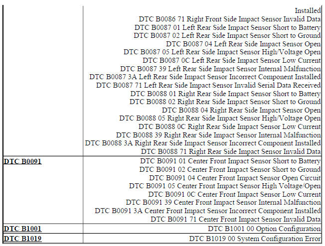
DIAGNOSTIC CODE INDEX
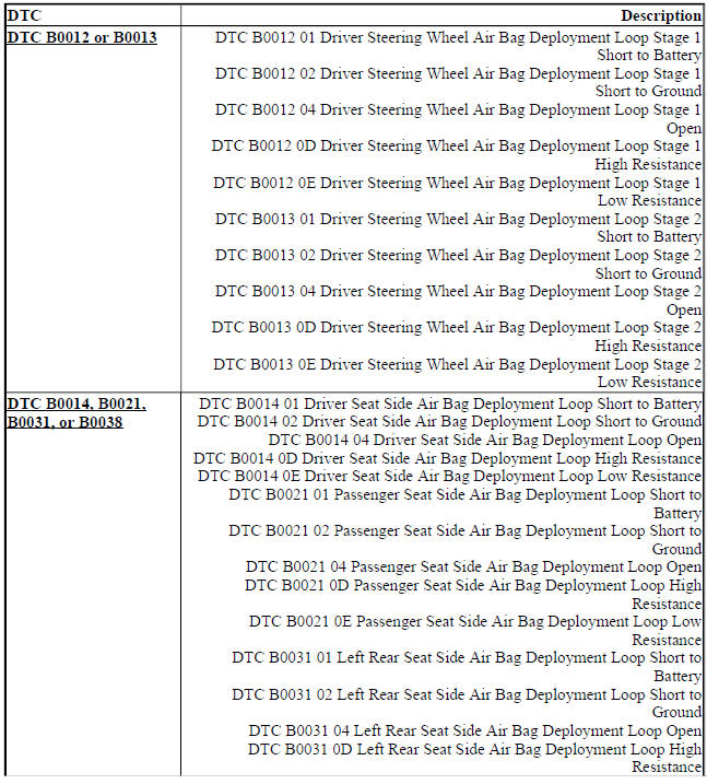
DTC B0012 OR B0013: DRIVER STEERING WHEEL AIR BAG DEPLOYMENT LOOP
Diagnostic Instructions
- Perform the Diagnostic System Check - Vehicle prior to using this diagnostic procedure.
- Review Strategy Based Diagnosis for an overview of the diagnostic approach.
- Diagnostic Procedure Instructions provides an overview of each diagnostic category
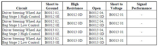
DTC Descriptors
DTC B0012 01
Driver Steering Wheel Air Bag Deployment Loop Stage 1 Short to Battery
DTC B0012 02
Driver Steering Wheel Air Bag Deployment Loop Stage 1 Short to Ground
DTC B0012 04
Driver Steering Wheel Air Bag Deployment Loop Stage 1 Open
DTC B0012 0D
Driver Steering Wheel Air Bag Deployment Loop Stage 1 High Resistance
DTC B0012 0E
Driver Steering Wheel Air Bag Deployment Loop Stage 1 Low Resistance
DTC B0013 01
Driver Steering Wheel Air Bag Deployment Loop Stage 2 Short to Battery
DTC B0013 02
Driver Steering Wheel Air Bag Deployment Loop Stage 2 Short to Ground
DTC B0013 04
Driver Steering Wheel Air Bag Deployment Loop Stage 2 Open
DTC B0013 0D
Driver Steering Wheel Air Bag Deployment Loop Stage 2 High Resistance
DTC B0013 0E
Driver Steering Wheel Air Bag Deployment Loop Stage 2 Low Resistance
Diagnostic Fault Information
Circuit/System Description
During a frontal crash of sufficient force the inflatable restraint sensing and diagnostic module (SDM) will allow current to flow through the deployment loop in order to deploy the steering wheel air bag. The SDM performs continuous diagnostic tests on the deployment loops to check for proper circuit continuity and for shorts to ground or voltage. There are 2 shorting bars used within the steering wheel air bag coil connector which will short together both steering wheel air bag stage 1 high control circuit and steering wheel air bag stage 1 low control circuit and both steering wheel air bag stage 2 high control circuit and steering wheel air bag stage 2 low control circuit when the connector is disconnected. This will help to prevent unwanted deployment of the steering wheel air bag during servicing.
Conditions for Running the DTC
Ignition voltage is between 9-16 V.
Conditions for Setting the DTC
B0012 01 stage 1 or B0013 01 stage 2
The steering wheel air bag deployment loop is shorted to voltage for 2 seconds.
B0012 02 stage 1 or B0013 02 stage 2
The steering wheel air bag deployment loop is shorted to ground for 2 seconds.
B0012 04 stage 1 or B0013 04 stage 2
The steering wheel air bag deployment loop is open for 2 seconds.
B0012 0D stage 1 or B0013 0D stage 2
The steering wheel air bag deployment loop resistance is greater than 4.4 ohms for 2 seconds
B0012 0E stage 1 or B0013 0E stage 2
The steering wheel air bag deployment loop resistance is less than 1.7 ohms for 2 seconds.
Action Taken When the DTC Sets
- The inflatable restraint sensing and diagnostic module requests the instrument cluster to illuminate the AIR BAG indicator.
- The inflatable restraint sensing and diagnostic module will store a DTC, however if an event occurs the system will still attempt deployment.
Conditions for Clearing the DTC
- The condition for setting the DTC is no longer exists.
- A history DTC will clear once 100 malfunction-free ignition cycles have occurred.
Diagnostic Aid
NOTE: The following diagnostic aids apply for both current and history DTCs.
A worn steering wheel air bag coil can cause a repeated history DTC to set. To verify this condition, turn the steering wheel 360 degrees in one direction then back 360 degrees in the other direction, multiple times, while viewing the scan tool Deployment Loop Resistance parameters.
An incorrectly installed connector position assurance (CPA) or incorrectly seated connector can cause a shorting bar to short both control circuits together. Check the connectors and CPAs if a DTC with symptom byte 02 or 0E is set, to ensure the shorting bars are not causing the circuits to be shorted together. Shorting bars are used in the locations listed below:
- Steering wheel air bag assembly
- Steering wheel air bag coil assembly
- Inline harness connectors
- Harness side of the inflatable restraint sensing and diagnostic module connector
Terminal fretting or incorrectly seated connector can cause an open/high resistance condition. Check the circuit terminals for fretting or incorrectly seated connector if a DTC with symptom byte 04 or 0D is set.
Reference Information
Schematic Reference
SIR Schematics (Encore), SIR Schematics (Trax)
Connector End View Reference
WIRING SYSTEMS AND POWER MANAGEMENT - COMPONENT CONNECTOR END VIEWS - INDEX - ENCORE WIRING SYSTEMS AND POWER MANAGEMENT - COMPONENT CONNECTOR END VIEWS - INDEX - TRAX
Description and Operation
Supplemental Inflatable Restraint System Description and Operation
Electrical Information Reference
- Circuit Testing
- Testing for Intermittent Conditions and Poor Connections
- Wiring Repairs
- Connector Repairs
Scan Tool Reference
Control Module References for scan tool information
Special Tools
EL-38125-580 Terminal Release Tool Kit
Circuit/System Verification
NOTE:
- Refer to SIR Service Precautions.
- Inspect all terminals for damage or corrosion when disconnecting connectors. Damage or corrosion in the following requires repair or replacement of the affected component/connector
- Driver steering wheel air bag
- Driver steering wheel air bag coil
- Inflatable restraint sensing and diagnostic module
- Air bag wiring harness connector
- Inflatable restraint sensing and diagnostic module wiring harness connector
- The connector and connector position assurance (CPA) may seat independent of each other. Both the connector and CPA should seat with an audible and/or tactile click. The CPA isolates the shorting-bars within the connector allowing the deployment circuit to operate properly. Replace any CPA that is damaged or missing.
- If the condition is intermittent or cannot be duplicated, disconnect the connectors and add dielectric grease / lubricant (Nyogel 760G or equivalent, meeting GM specification 9986087). This procedure will correct the high resistance condition due to terminal fretting corrosion.
- Verify the appropriate scan tool Deployment Loop Resistance parameters stay consistently between 2.1- 4.0 ohms without any spikes or dropouts while turning the steering wheel 360 degrees in one direction then back 360 degrees in the other direction.
- If less than 2.1 ohms or greater than 4.0 ohms
Refer to Circuit/System Testing.
- If there are spikes or dropouts
Replace the X85 Steering Wheel Air Bag Coil.
- If between 2.1-4.0 ohms without any spikes or dropouts
- Verify DTC B0012 or B0013 is only set as a history DTC.
- If the DTC is set as current
Refer to Circuit/System Testing.
- If the DTC is set as history
- Verify the scan tool Deployment Loop Resistance parameters stay consistently between 2.1-4.0 ohms without any drop outs or spikes while moving the harness near each connector listed below.
- X85 Steering Wheel Air Bag Coil
- F107 Steering Wheel Air Bag
- Any inline harness connector
- K36 Inflatable Restraint Sensing and Diagnostic Module
- If the reading is erratic while moving the harness, perform the following
- Inspect each connector terminal for damage or corrosion and repair as necessary
- Apply dielectric grease / lubricant (Nyogel 760G or equivalent, meeting GM specification 9986087) to each connector terminal
- Ensure each connector and CPA is correctly seated
- If between 2.1-4.0 ohms without any spikes or dropouts
- All OK.
Circuit/System Testing
- Ignition OFF, disconnect the scan tool and disconnect the appropriate harness connector listed below at the F107 Driver Steering Wheel Air Bag.
- DTC B0012 connector X1
- DTC B0013 connector X2
- Test for greater than 25 ohms between the control circuit terminal 1 and the control circuit terminal 2.
- If 25 ohms or less
- Disconnect the X1 harness connector at the K36 Inflatable Restraint Sensing and Diagnostic Module.
NOTE: Some connectors may be equipped with shorting bars as a safety component to prevent accidental deployment. When testing on a connector with shorting bars, the shorting bars must be disabled to ensure accurate test results. Insert an appropriate pick from EL- 38125-580 and depress the shorting bars above the appropriate terminals. This will lift the shorting bar from the terminal and allow accurate test results. Take care not to damage the connector, shorting bar, or terminal when depressing the shorting bar.
- Test for infinite resistance between the two control circuits.
- If less than infinite resistance, repair the short between the two circuits.
- If infinite resistance, replace the K36 Inflatable Restraint Sensing and Diagnostic Module.
- If greater than 25 ohms
- Ignition ON.
- Test for less than 11 V between each control circuit terminal listed below and ground:
- Control circuit terminal 1
- Control circuit terminal 2
- If 11 V or greater
- Ignition OFF, disconnect the X1 harness connector at the K36 Inflatable Restraint Sensing and Diagnostic Module, ignition ON.
- Test for less than 1 V between the control circuit and ground.
- If 1 V or greater, repair the short to voltage on the circuit.
- If less than 1 V, replace the K36 Inflatable Restraint Sensing and Diagnostic Module.
- If less than 11 V
- Ignition OFF.
- Test for greater than 25 ohms between each control circuit terminal listed below and ground:
- Control circuit terminal 1
- Control circuit terminal 2
- If 25 ohms or less
- Disconnect the X1 harness connector at the K36 Inflatable Restraint Sensing and Diagnostic Module.
NOTE:
Some connectors may be equipped with shorting bars as a safety component to prevent accidental deployment. When testing on a connector with shorting bars, the shorting bars must be disabled to ensure accurate test results. Insert an appropriate pick from EL- 38125-580 and depress the shorting bars above the appropriate terminals. This will lift the shorting bar from the terminal and allow accurate test results. Take care not to damage the connector, shorting bar, or terminal when depressing the shorting bar.
- Test for infinite resistance between the control circuit and ground.
- If less than infinite resistance, repair the short to ground on the circuit.
- If infinite resistance, replace the K36 Inflatable Restraint Sensing and Diagnostic Module.
- If greater than 25 ohms
- Install a 3 A fused jumper wire between the control circuit terminal 1 and the control circuit terminal 2, ignition ON.
- Verify DTC B0012 0E or B0013 0E is set while turning the steering wheel 360 degrees in one direction then back 360 degrees in the other direction.
If DTC B0012 0E or B0013 0E is not set
- Ignition OFF, disconnect the X1 harness connector at the K36 Inflatable Restraint Sensing and Diagnostic Module.
- Test for less than 2 ohms in the K85 Steering Wheel Airbag Coil and each control circuit end to end.
- If 2 ohms or greater, replace the X85 Steering Wheel Air Bag Coil or repair the open/high resistance in the circuit.
- If less than 2 ohms, replace the K36 Inflatable Restraint Sensing and Diagnostic Module.
- If DTC B0012 0E or B0013 0E is set
- Ignition OFF, connect the harness connector at the F107 Steering Wheel Air Bag, press in the CPA (if equipped) until an audible and/or tactile click is heard.
- Ignition ON, clear DTCs. Operate the vehicle within the Conditions for Running the DTC.
- Verify DTC B0012 or B0013 is not set.
- If DTC B0012 or B0013 is set
Test or replace the F107 Steering Wheel Air Bag.
- If DTC B0012 or B0013 is not set
- All OK.
Repair Instructions
Perform the Diagnostic Repair Verification after completing the repair.
- Steering Wheel Airbag Coil Replacement (Trax), Steering Wheel Airbag Coil Replacement (Encore)
- Steering Wheel Airbag Replacement (Encore), Steering Wheel Airbag Replacement (Trax) SIR/SRS Wiring Repairs
- Control Module References for inflatable restraint sensing and diagnostic module replacement, programming and setup
