Chevrolet Trax: DTC B2610
Diagnostic Instructions
- Perform the Diagnostic System Check - Vehicle prior to using this diagnostic procedure.
- Review Strategy Based Diagnosis for an overview of the diagnostic approach.
- Diagnostic Procedure Instructions provides an overview of each diagnostic category.
DTC Descriptors
DTC B2610 01
Passenger Compartment Dimming 1 Circuit Short to Battery
DTC B2610 02
Passenger Compartment Dimming 1 Circuit Short to Ground
DTC B2610 04
Passenger Compartment Dimming 1 Circuit Open
Diagnostic Fault Information
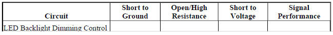
.jpg)
Circuit/System Description
The instrument panel dimmer switch is used to increase and decrease the brightness of the interior backlighting components. The instrument panel dimmer switch provides a voltage signal to the body control module (BCM) that will increase as the brightness of the lights are increased and decrease as the brightness of the lights are decreased. The BCM provides a low reference, signal, and B+ voltage reference circuits to the instrument panel dimmer switch. When the instrument panel dimmer switch is placed in the desired position, the dimmed voltage setting is applied from the instrument panel dimmer switch through the instrument panel dimmer switch signal circuit to the BCM. The BCM interprets the signal and applies a pulse width modulated (PWM) voltage through the light emitting diode (LED) dimming control circuits illuminating the interior backlighting to the requested level of brightness.
Conditions for Running the DTC
- Battery voltage must be between 9-16 V.
- Park lamps ON.
Conditions for Setting the DTC
DTC B2610 01
The BCM detects a short to battery in the LED backlight dimming control circuit terminal 8 X2 or the LED backlight dimming control circuit terminal 9 X7.
DTC B2610 02
The BCM detects a short to ground in the LED backlight dimming control circuit terminal 8 X2 or the LED backlight dimming control circuit terminal 9 X7.
DTC B2610 04
The BCM detects an open/high resistance in the LED backlight dimming control circuit terminal 8 X2 or the LED backlight dimming control circuit terminal 9 X7.
Actions Taken When the DTC Sets
The BCM will disable the LED backlight dimming control circuits.
Conditions for Clearing the DTC
- The condition responsible for setting the DTC no longer exists.
- A history DTC will clear once 100 consecutive malfunction-free ignition cycles have occurred.
Reference Information
Schematic Reference
Interior Lights Dimming Schematics (Encore) , Interior Lights Dimming Schematics (Trax)
Connector End View Reference
WIRING SYSTEMS AND POWER MANAGEMENT - COMPONENT CONNECTOR END VIEWS - INDEX - ENCORE WIRING SYSTEMS AND POWER MANAGEMENT - COMPONENT CONNECTOR END VIEWS - INDEX - TRAX
Description and Operation
Interior Lighting Systems Description and Operation
Electrical Information Reference
- Circuit Testing
- Connector Repairs
- Testing for Intermittent Conditions and Poor Connections
- Wiring Repairs
Scan Tool Reference
Control Module References for scan tool information
Circuit/System Testing
NOTE:
Each component with backlighting may need to be disconnected to isolate a short to voltage or short to ground. Use the schematics to identify the following:
- Backlighting components the vehicle is equipped with
- Each component's control and ground circuit terminals
- Component locations on the backlighting control circuit
- Ignition OFF, all doors closed, all accessories OFF, disconnect the harness connector at the component with inoperative backlighting. It may take up to 2 minutes for all vehicle systems to power down.
- Test for less than 15 ohms between the appropriate ground circuit terminal and ground.
- If 15 ohms or greater
- Ignition OFF.
- Test for less than 2 ohms in the ground circuit end to end.
- If 2 ohms or greater, repair the open/high resistance in the circuit.
- If less than 2 ohms, repair the open/high resistance in the ground connection.
- If less than 15 ohms
- Connect a test lamp between the appropriate control circuit terminal and ground, ignition ON.
- Verify the test lamp turns ON and OFF when commanding the LED Backlight Dimming ON and OFF with a scan tool.
- If the test lamp is always OFF
- Ignition OFF, disconnect the appropriate harness connector listed below at the K9 Body Control Module.
- X2 terminal 8
- X7 terminal 9
- Test for infinite resistance between the control circuit and ground.
- If less than infinite resistance, repair the short to ground on the circuit.
- If infinite resistance
- Test for less than 2 ohms in the control circuit end to end.
- If 2 ohms or greater, repair the open/high resistance in the circuit.
- If less than 2 ohms, replace the K9 Body Control Module.
- If the test lamp is always ON
- Ignition OFF, disconnect the appropriate harness connector listed below at the K9 Body Control Module, ignition ON.
- X2 terminal 8
- X7 terminal 9
- Test for less than 1 V between the control circuit terminal and ground.
- If 1 V or greater, repair the short to voltage on the circuit.
- If less than 1 V, replace the K9 Body Control Module
- If the test lamp turns ON and OFF
- Test or replace the component with inoperative backlighting.
Repair Instructions
Perform the Diagnostic Repair Verification after completing the repair.
- Instrument Panel Multifunction Switch Replacement (Encore)
- Headlamp Switch Replacement (Encore) , Headlamp Switch Replacement (Trax)
- Sunroof Switch Replacement
- Transmission Control Replacement
- Radio and Telephone Control Switch Replacement
- Control Module References for BCM replacement, programming, and setup
