Chevrolet Trax: DTC B2645
Diagnostic Instructions
- Perform the Diagnostic System Check - Vehicle prior to using this diagnostic procedure.
- Review Strategy Based Diagnosis for an overview of the diagnostic approach.
- Diagnostic Procedure Instructions provides an overview of each diagnostic category.
DTC Descriptors
DTC B2645 03
Ambient Light Sensor Circuit Low Voltage
DTC B2645 07
Ambient Light Sensor Circuit High Voltage
Diagnostic Fault Information
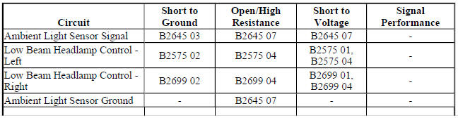
.jpg)
Circuit/System Description
The ambient light sensor is used to monitor outside lighting conditions. The body control module (BCM) provides a 5-volt reference signal to the ambient light sensor. Depending on outside lighting conditions, the ambient light sensor provides a voltage signal to the BCM that will vary between 0.2 and 4.9 volts. The BCM monitors the ambient light sensor signal circuit to determine if outside lighting conditions are correct for either daytime running lights (DRL) or automatic headlamp system control when the headlamp switch is in the AUTO position. In daylight conditions, the BCM will command the low beam headlamps (DRLs) ON by applying low voltage to the low beam headlamp control circuits illuminating the low beam headlamps at reduced intensity.
Any function or condition that turns on the headlamps will cancel DRL operation.
Conditions for Running the DTC
Battery voltage must be between 9-16 V.
Conditions for Setting the DTC
DTC B2645 03
The BCM detects a short to ground in the ambient light sensor signal circuit.
DTC B2645 07
- The BCM detects a short to voltage or an open/high resistance in the ambient light sensor signal circuit.
- The BCM detects an open/high resistance in the ambient light sensor ground circuit.
Actions Taken When the DTC Sets
- Automatic headlamp system and daytime running lamps are inoperative.
- The BCM defaults to low light status and commands the low beam headlamps ON.
Conditions for Clearing the DTC
- The condition responsible for setting the DTC no longer exists.
- A history DTC will clear once 100 consecutive malfunction-free ignition cycles have occurred.
Reference Information
Schematic Reference
Headlights/Daytime Running Lights (DRL) Schematics (Encore) , Headlights/Daytime Running Lights (DRL) Schematics (Trax)
Connector End View Reference
WIRING SYSTEMS AND POWER MANAGEMENT - COMPONENT CONNECTOR END VIEWS - INDEX - ENCORE WIRING SYSTEMS AND POWER MANAGEMENT - COMPONENT CONNECTOR END VIEWS - INDEX - TRAX
Description and Operation
Exterior Lighting Systems Description and Operation
Electrical Information Reference
- Circuit Testing
- Connector Repairs
- Testing for Intermittent Conditions and Poor Connections
- Wiring Repairs
Scan Tool Reference
Control Module References for scan tool information
Circuit/System Testing
- Ignition OFF, scan tool disconnected, all doors closed, all accessories OFF, open and close drivers door, disconnect the harness connector at the B10 Ambient Light Sensor. It may take up to 2 minutes for all vehicle systems to power down.
- Test for less than 15 ohms between the ground circuit terminal 6 and ground.
- If 15 ohms or greater
- Ignition OFF.
- Test for less than 2 ohms in the ground circuit end to end.
- If 2 ohms or greater, repair the open/high resistance in the circuit.
- If less than 2 ohms, repair the open/high resistance in the ground connection.
- If less than 15 ohms
- Ignition ON.
- Verify the scan tool Ambient Light Sensor parameter is greater than 4.65 V.
- If 4.65 V or less
- Ignition OFF, disconnect the X2 harness connector at the K9 Body Control Module.
- Test for infinite resistance between the signal circuit terminal 5 and ground.
- If less than infinite resistance, repair the short to ground on the circuit.
- If infinite resistance, replace the K9 Body Control Module.
- If greater than 4.65 V
- Install a 3 A fused jumper wire between the signal circuit terminal 5 and the ground circuit terminal 6.
- Verify the scan tool Ambient Light Sensor parameter is less than 0.196 V.
- If 0.196 V or greater
- Ignition OFF, disconnect the X2 harness connector at the K9 Body Control Module, ignition ON.
- Test for less than 1 V between the signal circuit terminal 5 and ground.
- If 1 V or greater, repair the short to voltage on the circuit.
- If less than 1 V
- Test for less than 2 ohms in the signal circuit end to end.
- If 2 ohms or greater, repair the open/high resistance in the circuit.
- If less than 2 ohms, replace the K9 Body Control Module.
- If less than 0.196 V
- Test or replace the B10 Ambient Light Sensor.
Repair Instructions
Perform the Diagnostic Repair Verification after completing the repair.
- Sun Load Temperature Sensor Replacement
- Control Module References for BCM replacement, programming, and setup
