Chevrolet Trax: DTC B2345 (WITHOUT MEMORY A45): Seat heater disable circuit low voltage/high temperature
Diagnostic Instructions
- Perform the Diagnostic System Check - Vehicle prior to using this diagnostic procedure.
- Review Strategy Based Diagnosis for an overview of the diagnostic approach.
- Diagnostic Procedure Instructions provides an overview of each diagnostic category
DTC Descriptors
DTC B2345 13
Seat Heater Disable Circuit Low Voltage/High Temperature
Diagnostic Fault Information
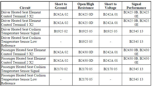
Circuit/System Description
The heated seat temperature sensor is located in the seat cushion just under the seat cover with the seat heating element. The seat heating control module supplies a 5 V reference voltage through the temperature sensor signal circuit and a ground through the low reference circuit to the sensor. The module monitors the voltage of the sensor signal circuit to determine the temperature of the seat. The temperature sensor varies in resistance based on the temperature of the heating element causing the signal voltage to change. Once the seat reaches the set temperature, the module will then cycle the control circuit of the heating elements ON and OFF in order to maintain the desired seat temperature based on the feedback voltage from the sensor.
Conditions for Running the DTC
The seat heating control module must be powered.
Conditions for Setting the DTC
B2345 13
Any temperature sensor input that remains below 1.5 V for more than 1 s.
Action Taken When the DTC Sets
The heated seat function for both seats will be disabled.
Conditions for Clearing the DTC
- The current DTC will clear and set the code to history 3 s after the reference voltage returns to the normal operating range and the ignition is cycled OFF then back to ACC or RUN.
- The history DTC will clear after 40 consecutive fault-free ignition cycles have occurred.
Reference Information
Schematic Reference
Heated/Cooled Seat Schematics (Encore), Heated/Cooled Seat Schematics (Trax)
Connector End View Reference
WIRING SYSTEMS AND POWER MANAGEMENT - COMPONENT CONNECTOR END VIEWS - INDEX - ENCORE WIRING SYSTEMS AND POWER MANAGEMENT - COMPONENT CONNECTOR END VIEWS - INDEX - TRAX
Description and Operation
Heated Seats Description and Operation
Electrical Information Reference
- Circuit Testing
- Connector Repairs
- Testing for Intermittent Conditions and Poor Connections
- Wiring Repairs
Scan Tool Reference
Control Module References for scan tool information
Circuit/System Testing
- Ignition OFF, disconnect the X2 and X3 harness connectors at the K29 Seat Heating Control Module
- Test for greater than 3.0 kohms between the signal and the low reference circuit terminals listed below:
- Driver seat cushion terminal 3 X3 and terminal 13 X2
- Passenger seat cushion terminal 4 X3 and terminal 14 X2
- If less than 3.0 kohms
- Ignition OFF, disconnect the harness connector at the appropriate E14 Seat Heating Element - Cushion.
- Test for Infinite resistance between the signal and low reference circuits.
- If less than infinite resistance, repair the short between the circuits.
- If infinite resistance, test or replace the E14 Seat Heating Element - Cushion.
- If greater than 3.0 kohms
- Replace the K29 Seat Heating Control Module.
Repair Instructions
Perform the Diagnostic Repair Verification after completing the repair.
- Driver or Passenger Seat Cushion Heater Replacement
- Control Module References for K29 Seat Heating Control Module replacement, setup and programming
READ NEXT:
 DTC B2345 (WITH MEMORY A45): Seat heater disable circuit low voltage high/temperature
Diagnostic Instructions
Perform the Diagnostic System Check - Vehicle prior to using this
diagnostic procedure.
Review Strategy Based Diagnosis for an overview of the diagnostic
approach.
Diag
DTC B2425 OR B2430 (WITHOUT MEMORY A45): Seat cushion heater circuit
Diagnostic Instructions
Perform the Diagnostic System Check - Vehicle prior to using this
diagnostic procedure.
Review Strategy Based Diagnosis for an overview of the diagnostic
approach.
Diag
DTC B2425 OR B2430 (WITH MEMORY A45): Seat cushion heater circuit
Diagnostic Instructions
Perform the Diagnostic System Check - Vehicle prior to using this
diagnostic procedure.
Review Strategy Based Diagnosis for an overview of the diagnostic
approach.
Diag
SEE MORE:
Paint and Coatings - Introduction
BASECOAT/CLEARCOAT PAINT SYSTEMS
WARNING: Exposure to isocyanates during paint preparation and
application
processes can cause severe breathing problems. Read and follow all of
the instructions from the manufacturers of painting materials, equipment,
and protective gear.
All paint finish repairs of
Heater and air conditioning evaporator and blower upper case replacement
Fig. 49: Heater And Air Conditioning Evaporator And Blower Upper Case
Heater and Air Conditioning Evaporator and Blower Upper Case Replacement
HEATER AND AIR CONDITIONING EVAPORATOR AND BLOWER LOWER CASE REPLACEMENT
Fig. 50: Heater And Air Conditioning Evaporator And Blower Lower Case
Heater a
