Chevrolet Trax: DTC B2345 (WITH MEMORY A45): Seat heater disable circuit low voltage high/temperature
Diagnostic Instructions
- Perform the Diagnostic System Check - Vehicle prior to using this diagnostic procedure.
- Review Strategy Based Diagnosis for an overview of the diagnostic approach.
- Diagnostic Procedure Instructions provides an overview of each diagnostic category.
DTC Descriptors
DTC B2345 13
Seat Heater Disable Circuit Low Voltage High/Temperature
Diagnostic Fault Information
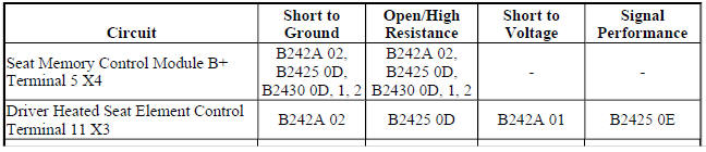
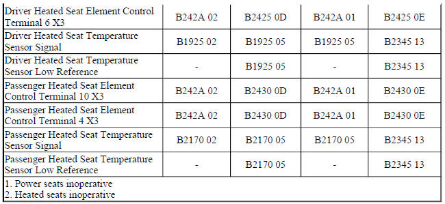
Circuit/System Description
The seat memory control module controls seat heating operation for both the driver and front passenger seats.
The heating elements are controlled through individual high side and low side control circuits. The low side control circuits for both seats are connected to a common reference point internal to the module. This reference point is biased to approximately 2.5 V. Before the seat memory control module will allow heated seat operation, it checks to see if this biased voltage is shorted to ground or voltage. Once the module verifies that it is not closing to a shorted heating element, it allows for heated seat operation. The module will then continue to monitor the heating elements for a shorted circuit.
Conditions for Running the DTC
The seat memory control module must be powered.
Conditions for Setting the DTC
B2345 13
Any temperature sensor input that remains below 1.5 V for more than 1 s.
Action Taken When the DTC Sets
The heated seat function for both front seats will be disabled.
Conditions for Clearing the DTC
- The current DTC will clear and set the code to history 3 s after the reference voltage returns to the normal operating range and the ignition is cycled OFF then back to ACC or RUN.
- The history DTC will clear after 40 consecutive fault-free ignition cycles have occurred.
Reference Information
Schematic Reference
Heated/Cooled Seat Schematics (Encore), Heated/Cooled Seat Schematics (Trax)
Connector End View Reference
WIRING SYSTEMS AND POWER MANAGEMENT - COMPONENT CONNECTOR END VIEWS - INDEX - ENCORE WIRING SYSTEMS AND POWER MANAGEMENT - COMPONENT CONNECTOR END VIEWS - INDEX - TRAX
Description and Operation
Heated Seats Description and Operation
Electrical Information Reference
- Circuit Testing
- Connector Repairs
- Testing for Intermittent Conditions and Poor Connections
- Wiring Repairs
Scan Tool Reference
Control Module References for scan tool information
Circuit/System Testing
- Ignition OFF, disconnect the X2 and X3 harness connectors at the K40 Seat Memory Control Module.
- Test for greater than 3.0 kohms between the signal and the low reference circuits listed below:
- E14B driver seat cushion terminal 16 X2 and terminal 12 X3
- E14D passenger seat cushion terminal 7 X2 and terminal 1 X3
- If less than 3.0 kohms
- Ignition OFF, disconnect the harness connector at the appropriate E14B or E14D Seat Heating Element - Cushion.
- Test for Infinite resistance between the signal and low reference circuits.
- If less than infinite resistance, repair the short between the circuits.
- If infinite resistance, test or replace the E14 Seat Heating Element - Cushion.
- If greater than 3.0 kohms
- Replace the K40 Seat Memory Control Module.
Component Testing
Seat Cushion Heating Element
- Ignition OFF, disconnect the harness connector at the appropriate E14B or E14D Seat Heating Element - Cushion.
- Test for 500 ohms-300 kohms between the signal circuit terminal B and the low reference circuit terminal C.
- If not between 500 ohms-300 kohms
Replace the E14 Seat Heating Element - Cushion.
- If between 500 ohms-300 kohms
- All OK.
Repair Instructions
Perform the Diagnostic Repair Verification after completing the repair.
- Driver or Passenger Seat Cushion Heater Replacement
- Control Module References for K40 Seat Memory Control Module replacement, programming and setup
READ NEXT:
 DTC B2425 OR B2430 (WITHOUT MEMORY A45): Seat cushion heater circuit
Diagnostic Instructions
Perform the Diagnostic System Check - Vehicle prior to using this
diagnostic procedure.
Review Strategy Based Diagnosis for an overview of the diagnostic
approach.
Diag
DTC B2425 OR B2430 (WITH MEMORY A45): Seat cushion heater circuit
Diagnostic Instructions
Perform the Diagnostic System Check - Vehicle prior to using this
diagnostic procedure.
Review Strategy Based Diagnosis for an overview of the diagnostic
approach.
Diag
DTC B242A (WITHOUT MEMORY A45): Seat heaters common circuit
Diagnostic Instructions
Perform the Diagnostic System Check - Vehicle prior to using this
diagnostic procedure.
Review Strategy Based Diagnosis for an overview of the diagnostic
approach.
Diag
SEE MORE:
Air conditioning compressor malfunction (C60)
Diagnostic Instructions
Perform the Diagnostic System Check - Vehicle prior to using this
diagnostic procedure.
Review Strategy Based Diagnosis for an overview of the diagnostic
approach.
Diagnostic Procedure Instructions provides an overview of each
diagnostic category.
Diagnostic Fault
Navigation system - voice recognition malfunction
Diagnostic Instructions
Perform the Diagnostic System Check - Vehicle prior to using this
diagnostic procedure.
Review Strategy Based Diagnosis for an overview of the diagnostic
approach.
Diagnostic Procedure Instructions provide an overview of each diagnostic
category.
Diagnostic Fault I
