Chevrolet Trax: DTC B2425 OR B2430 (WITH MEMORY A45): Seat cushion heater circuit
Diagnostic Instructions
- Perform the Diagnostic System Check - Vehicle prior to using this diagnostic procedure.
- Review Strategy Based Diagnosis for an overview of the diagnostic approach.
- Diagnostic Procedure Instructions provides an overview of each diagnostic category
DTC Descriptors
DTC B2425 0B
Driver Seat Cushion Heater Circuit High Current
DTC B2425 0D
Driver Seat Cushion Heater Circuit High Resistance
DTC B2425 0E
Driver Seat Cushion Heater Circuit Low Resistance
DTC B2430 0B
Passenger Seat Cushion Heater Circuit High Current
DTC B2430 0D
Passenger Seat Cushion Heater Circuit High Resistanc
DTC B2430 0E
Passenger Seat Cushion Heater Circuit Low Resistance
Diagnostic Fault Information
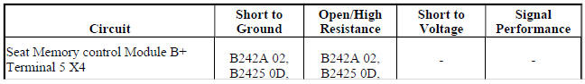
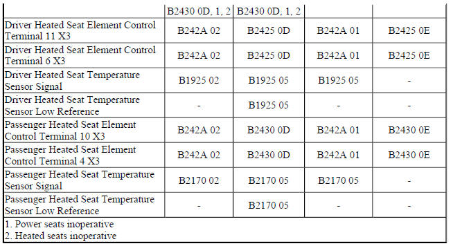
Circuit/System Description
The driver and front passenger heated seats are controlled by the seat memory control module that is located under the driver seat cushion. When the heated seat is active, the module applies power through a common voltage supply circuit to the seat heater elements. The module controls the seat temperature by providing a pulse width modulation (PWM) ground through the seat heater element control circuit to the heater elements. The module then monitors the current flow through the heating elements and the rate of change of the temperature sensor to verify correct heated seat operation.
Conditions for Running the DTC
- DTC B1325 must not be present.
- The seat memory control module must be powered and the heated seat must be enabled.
Conditions for Setting the DTC
B2425 0D or B2430 0D
By measuring current and voltage output to the seat heating elements every 10 s, the seat memory control module calculates that the heating element resistance is above the maximum resistance.
B2425 0B, B2425 0E, B2430 0B, or B2430 0E
By measuring current and voltage output to the seat heating elements every 10 s, the seat memory control module calculates that the heating element resistance is below the minimum resistance.
Action Taken When the DTC Sets
The heated seat function for the affected seat will be disabled.
Conditions for Clearing the DTC
- The current DTC clears when the malfunction is no longer present, and the power mode changes to OFF then back to ACC or RUN.
- The history DTC will clear after 40 consecutive fault-free ignition cycles have occurred.
Reference Information
Schematic Reference
Heated/Cooled Seat Schematics (Encore), Heated/Cooled Seat Schematics (Trax)
Connector End View Reference
WIRING SYSTEMS AND POWER MANAGEMENT - COMPONENT CONNECTOR END VIEWS - INDEX - ENCORE WIRING SYSTEMS AND POWER MANAGEMENT - COMPONENT CONNECTOR END VIEWS - INDEX - TRAX
Description and Operation
Heated Seats Description and Operation
Electrical Information Reference
- Circuit Testing
- Connector Repairs
- Testing for Intermittent Conditions and Poor Connections
- Wiring Repairs
Scan Tool Reference
Control Module References for scan tool information
Circuit/System Testing
B2425 0B, B2425 0D, or B2425 0E
- Ignition OFF, disconnect the X4 harness connector at the K40 Seat Memory Control Module, ignition ON.
- Verify a test lamp illuminates between the B+ circuit terminal 5 and ground.
- If the test lamp does not illuminate
- Ignition OFF.
- Test for infinite resistance between the B+ circuit and ground.
- If less than infinite resistance, repair the short to ground on the circuit.
- If infinite resistance
- Test for less than 2 ohms in the B+ circuit end to end.
- If 2 ohms or greater, repair the open/high resistance in the circuit.
- If less than 2 ohms, verify the fuse is not open and there is voltage at the fuse.
- If the test lamp illuminates
- Ignition OFF, connect the X4 harness connector at the K40 Seat Memory Control Module and disconnect the harness connector at the E14A Seat Heating Element - Driver Back.
NOTE: Element resistance must be measured twice to ensure that all failure conditions are simulated. First with the seat unoccupied, then with the seat occupied.
- Test for 0.5-2.0 ohms between control circuit terminal A and control circuit terminal B.
- If not between 0.5-2.0 ohms
Replace the E14A Seat Heating Element - Driver Back.
- If between 0.5-2.0 ohms
- Connect the harness connector at the E14A Seat Heating Element - Driver Back and disconnect the X3 harness connector at the K40 Seat Memory Control Module.
- Test for 1-5 ohms between control circuit terminal 11 and control circuit terminal 6.
- If less than 1 ohms
- Ignition OFF, disconnect the harness connector at the E14B Seat Heating Element - Driver Cushion.
- Test for infinite resistance between the control circuits.
- If less than infinite resistance, repair the short between the circuits.
- If infinite resistance, test or replace the E14B Seat Heating Element - Driver Cushion.
- If greater than 5 ohms
- Ignition OFF, disconnect the harness connector at the E14B Seat Heating Element - Driver Cushion.
- Test for less than 2 ohms in the control circuits end to end.
- If 2 ohms or greater, repair the open/high resistance in the circuit.
- If less than 2 ohms, test or replace the E14B Seat Heating Element - Driver Cushion.
- If between 1-5 ohms
- Replace the K40 Seat Memory Control Module.
B2430 0B, B2430 0D, or B2430 0E
- Ignition OFF, disconnect the X4 harness connector at the K40 Seat Memory Control Module, ignition ON.
- Verify a test lamp illuminates between the B+ circuit terminal 5 and ground.
- If the test lamp does not illuminate
- Ignition OFF.
- Test for less than 2 ohms in the B+ circuit end to end.
- If 2 ohms or greater, repair the open/high resistance in the circuit.
- If less than 2 ohms, verify the fuse is not open and there is voltage at the fuse.
- If the test lamp illuminates
- Ignition OFF, connect the X4 harness connector at the K40 Seat Memory Control Module and disconnect the harness connector at the E14C Seat Heating Element - Passenger Back.
NOTE:
Element resistance must be measured twice to ensure that all failure conditions are simulated. First with the seat unoccupied, then with the seat occupied.
- Test for 0.5-2.0 ohms between control circuit terminal A and control circuit terminal B.
- If not between 0.5-2.0 ohms
Replace the E14C Seat Heating Element - Passenger Back.
- If between 0.5-2.0 ohms
- Connect the harness connector at the E14C Seat Heating Element - Passenger Back and disconnect the X3 harness connector at the K40 Seat Memory Control Module.
- Test for 1-5 ohms between control circuit terminal 10 and control circuit terminal 4.
- If less than 1 ohms
- Ignition OFF, disconnect the harness connector at the E14D Seat Heating Element - Passenger Cushion.
- Test for infinite resistance between the control circuits.
- If less than infinite resistance, repair the short between the circuits.
- If infinite resistance, test or replace the E14D Seat Heating Element - Passenger Cushion.
- If greater than 5 ohms
- Ignition OFF, disconnect the harness connector at the E14D Seat Heating Element - Passenger Cushion.
- Test for less than 2 ohms in the control circuits end to end.
- If 2 ohms or greater, repair the open/high resistance in the circuit.
- If less than 2 ohms, test or replace the E14D Seat Heating Element - Passenger Cushion.
- If between 1-5 ohms
- Replace the K40 Seat Memory Control Module.
Repair Instructions
Perform the Diagnostic Repair Verification after completing the repair.
- Driver or Passenger Seat Back Cushion Heater Replacement
- Driver or Passenger Seat Cushion Heater Replacement
- Control Module References for K40 Seat Memory Control Module replacement, programming and setup
