Chevrolet Trax: DTC B242A (WITH MEMORY A45): Seat heaters common circuit
Diagnostic Instructions
- Perform the Diagnostic System Check - Vehicle prior to using this diagnostic procedure.
- Review Strategy Based Diagnosis for an overview of the diagnostic approach.
- Diagnostic Procedure Instructions provides an overview of each diagnostic category.
DTC Descriptors
DTC B242A 01
Seat Heaters Common Circuit Short to Battery
DTC B242A 02
Seat Heaters Common Circuit Short to Ground
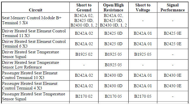
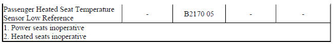
Diagnostic Fault Information
Circuit/System Description
The seat memory control module controls seat heating operation for both the driver and front passenger seats.
The heating elements are controlled through individual high side and low side control circuits. The low side control circuits for both seats are connected to a common reference point internal to the module. This reference point is biased to approximately 2.5 V. Before the seat memory control module will allow heated seat operation, it checks to see if this biased voltage is shorted to ground or voltage. Once the module verifies that it is not closing to a shorted heating element, it allows for heated seat operation. The module will then continue to monitor the heating elements for a shorted circuit.
Conditions for Running the DTC
- DTC B1325 must not be present.
- The seat memory control module must be powered.
Conditions for Setting the DTC
B242A 01
The seat memory control module detects a short to voltage on the heater element control circuits.
B242A 02
The seat memory control module detects a short to ground on the heater element control circuits.
Action Taken When the DTC Sets
The heated seat function for both seats will be disabled.
Conditions for Clearing the DTC
- The current DTC will clear and set a history code 3 s after the reference voltage returns to normal operating range and the ignition is cycled OFF then back to ACC or RUN.
- The history DTC will clear after 40 consecutive fault-free ignition cycles have occurred.
Reference Information
Schematic Reference
Heated/Cooled Seat Schematics (Encore), Heated/Cooled Seat Schematics (Trax)
Connector End View Reference
WIRING SYSTEMS AND POWER MANAGEMENT - COMPONENT CONNECTOR END VIEWS - INDEX - ENCORE WIRING SYSTEMS AND POWER MANAGEMENT - COMPONENT CONNECTOR END VIEWS - INDEX - TRAX
Description and Operation
Heated Seats Description and Operation
Electrical Information Reference
- Circuit Testing
- Connector Repairs
- Testing for Intermittent Conditions and Poor Connections
- Wiring Repairs
Scan Tool Reference
Control Module References for scan tool information
Circuit/System Testing
- Ignition OFF, disconnect the X4 harness connector at the K40 Seat Memory Control Module, ignition ON.
- Verify a test lamp illuminates between the B+ circuit terminal 5 and ground.
If the test lamp does not illuminate
- Ignition OFF.
- Test for infinite resistance between the B+ circuit and ground.
- If less than infinite resistance, repair the short to ground on the circuit.
- If infinite resistance
- Test for less than 2 ohms in the B+ circuit end to end.
- If 2 ohms or greater, repair the open/high resistance in the circuit.
- If less than 2 ohms, verify the fuse is not open and there is voltage at the fuse.
- If the test lamp illuminates
- Ignition OFF, connect the X4 harness connector at the K40 Seat Memory Control Module and disconnect the X3 harness connector at the K40 Seat Memory Control Module.
- Test for infinite resistance between the control circuit terminals listed below and ground:
- Terminal 11
- Terminal 10
- If less than infinite resistance
Repair the short to ground on the circuit.
- If infinite resistance
- Ignition ON.
- Test for less than 1 V between the control circuit terminals listed below and ground:
- Terminal 11
- Terminal 10
- If 1 V or greater
Repair the short to voltage on the circuit.
- If less than 1 V
- Replace the K40 Seat Memory Control Module.
Repair Instructions
Perform the Diagnostic Repair Verification after completing the repair.
Control Module References for K40 Seat Memory Control Module replacement, programming and setup
SYMPTOMS - SEAT HEATING AND COOLING
NOTE: The following steps must be completed before using the symptom tables.
- When diagnosing a heated seat system condition perform the Diagnostic System Check - Vehicle , before using the symptom tables in order to verify that all of the following are true:
- There are no DTCs set.
- The control module(s) can communicate via the serial data link.
- Review the system operation in order to familiarize yourself with the system functions. Refer to Heated Seats Description and Operation.
Visual/Physical Inspection
- Inspect for aftermarket devices which could affect the operation of the power seats. Refer to Checking Aftermarket Accessories .
- Inspect the easily accessible or visible system components for obvious damage or conditions which could cause the symptom.
- Inspect the seat adjuster track for conditions which may cause binding or objects within the seat adjustment range which obstruct movement or interfere with wiring.
Intermittent
Faulty electrical connections or wiring may be the cause of intermittent conditions. Refer to Testing for Intermittent Conditions and Poor Connections .
Symptom List
Refer to the Front Heated Seat Malfunction (Without Memory A45), Front Heated Seat Malfunction (With Memory A45) diagnostic procedure in order to diagnose the symptom.
READ NEXT:
 Front heated seat malfunction (without memory A45)
Diagnostic Instructions
Perform the Diagnostic System Check - Vehicle prior to using this
diagnostic procedure.
Review Strategy Based Diagnosis for an overview of the diagnostic
approach.
Diag
Front heated seat malfunction (with memory A45)
Diagnostic Instructions
Perform the Diagnostic System Check - Vehicle prior to using this
diagnostic procedure.
Review Strategy Based Diagnosis for an overview of the diagnostic
approach.
Diag
Seat heating and cooling - Repair instructions
FRONT SEAT HEATER CONTROL MODULE REPLACEMENT
Fig. 3: Front Seat Heater Control Module
Front Seat Heater Control Module Replacement
DRIVER OR PASSENGER SEAT BACK CUSHION HEATER REPLACEMENT
Fig.
SEE MORE:
OnStar
If the vehicle is equipped with
OnStar and has an active
subscription, additional data may be
collected through the OnStar
system. This includes information
about the vehicle's operation;
collisions involving the vehicle; the
use of the vehicle and its features;
and, in certain situations, the
locat
Drive Range, Fifth Gear - Gen 2/Hybrid
Fig. 15: Drive Range, Fifth Gear -- Gen 2/Hybrid Fluid Flow Diagram
Drive Range, Sixth Gear (Gen 2/Hybrid)
As vehicle speed increases, the transmission control module (TCM) processes
input signals from the automatic
transmission input and output speed sensors, the throttle position sensor and
ot
