Chevrolet Trax: Drive Range, Fifth Gear - Gen 2/Hybrid
.jpg)
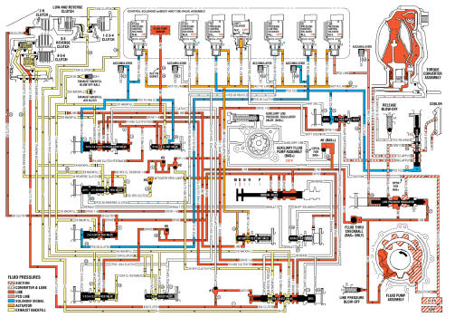
Fig. 15: Drive Range, Fifth Gear -- Gen 2/Hybrid Fluid Flow Diagram
Drive Range, Sixth Gear (Gen 2/Hybrid)
As vehicle speed increases, the transmission control module (TCM) processes input signals from the automatic transmission input and output speed sensors, the throttle position sensor and other vehicle sensors to determine the precise moment to command ON the normally-low 26 pressure control solenoid. At the same time, the normally-low 35R pressure control solenoid is commanded OFF and the transmission shifts into Sixth gear.
2-6 Clutch Applies
26 Pressure Control (PC) Solenoid
The 26 PC solenoid is commanded ON, allowing actuator feed limit fluid to enter the PCS 26 clutch fluid circuit. PCS 26 clutch fluid is then routed through orifice #24 to the 2-6 clutch regulator valve.
2-6 Clutch Regulator Valve
PCS 26 clutch fluid, at the 2-6 clutch regulator valve, opposes 2-6 clutch regulator valve spring force and orificed 26 clutch fluid pressure to regulate drive fluid pressure into the 26 clutch circuit. 26 clutch fluid is then routed through orifice #22 to the 2-6 clutch assembly in the transmission case, and through orifice #4 to the spring end of the 2-6 clutch regulator valve.
2-6 Clutch
The 26 clutch fluid from the 2-6 clutch regulator valve is routed through the transmission case to the 2-6 clutch piston assembly. The 26 clutch fluid pressure moves the piston against 2-6 clutch spring force to apply the 2-6 clutch plates.
Accumulator
PCS 26 clutch fluid is also routed to an accumulator valve. The accumulator valve is used to dampen any pressure irregularities occurring in the PCS 26 clutch fluid circuit. This helps to control clutch apply fluid pressure and clutch apply feel.
3-5 Reverse Clutch Releases
35R Pressure Control (PC) Solenoid
The 35R PC solenoid is commanded OFF allowing PCS 35 reverse clutch fluid from the 3-5-reverse clutch regulator valve to exhaust.
3-5-Reverse Clutch Regulator Valve
PCS 35 reverse clutch fluid exhausts, allowing 3-5-reverse clutch regulator valve spring force to move the 3-5- reverse clutch regulator valve to the released position. This allows exhausting 35 reverse clutch fluid pressure to pass into the exhaust backfill circuit in order to assist the 3-5-reverse clutch piston spring to quickly release the 3-5-reverse clutch.
3-5-Reverse Clutch
3-5-reverse clutch spring force, assisted by exhaust backfill pressure, moves the 3-5-reverse clutch piston to release the 3-5-reverse clutch plates and force 35 reverse clutch fluid to exhaust from the 3-5-reverse and 4-5-6 clutch housing assembly. The exhausting 35 reverse clutch fluid pressure is routed to the 3-5-reverse clutch regulator valve where it enters the exhaust backfill circuit.
Drive Range, Sixth Gear - Gen 2/Hybrid

Fig. 16: Drive Range, Sixth Gear -- Gen 2/Hybrid Fluid Flow Diagram

