Chevrolet Trax Owners & Service Manuals

Chevrolet Trax: Fluid passages (GEN 2/HYBRID)

Torque Converter and Differential Housing - Case Side

Fig. 17: Torque Converter and Differential Housing -- Case Side

Torque Converter and Differential Housing - Case Side

Fluid Pump Body - Fluid Pump Cover Side

Fig. 18: Fluid Pump Body -- Fluid Pump Cover Side

Fluid Pump Body - Fluid Pump Cover Side

Fluid Pump Cover - Fluid Pump Body Side

Fig. 19: Fluid Pump Cover -- Fluid Pump Body Side

Fluid Pump Cover - Fluid Pump Body Side

Case - Torque Converter and Differential Housing Side

Fig. 20: Case -- Torque Converter and Differential Housing Side

Case - Torque Converter and Differential Housing Side

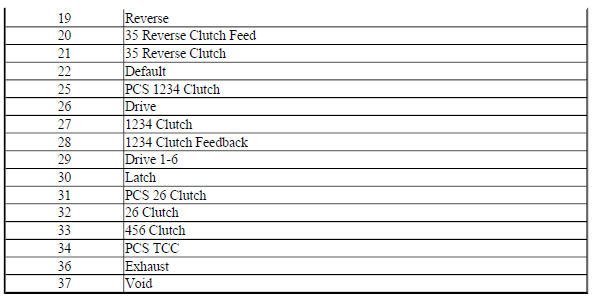
Case - Control Valve Body Side

Fig. 21: Case -- Control Valve Body Side Components Name

Case - Control Valve Body Side

Control Valve Body Spacer Plate Assembly - Case Side

Fig. 22: Control Valve Body Spacer Plate Assembly -- Case Side
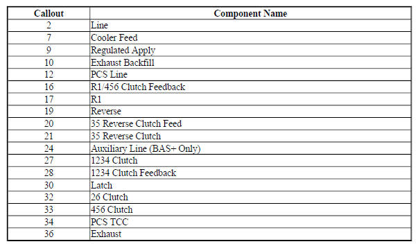

Control Valve Body Spacer Plate Assembly - Case Side

Control Valve Body - Case Side

Fig. 23: Control Valve Body -- Case Side

Control Valve Body - Case Side

Control Valve Body - Case Side

Control Valve Body - Channel Plate Side

Fig. 24: Control Valve Body -- Channel Plate Side

Control Valve Body - Channel Plate Side

Control Valve Body - Channel Plate Side

Channel Plate to Valve Body Spacer Plate Assembly - Channel Plate Side

Fig. 25: Channel Plate to Valve Body Spacer Plate Assembly -- Channel Plate Side

Channel Plate to Valve Body Spacer Plate Assembly - Channel Plate Side

Channel Plate - Control Valve Body Side

Fig. 26: Channel Plate -- Control Valve Body Side

Channel Plate - Control Valve Body Side

Channel Plate - Control Solenoid (w/Body and TCM) Valve Assembly Side

Fig. 27: Channel Plate -- Control Solenoid (w/Body and TCM) Valve Assembly Side
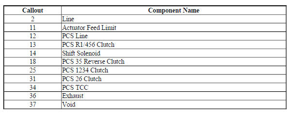

Channel Plate - Control Solenoid (w/Body and TCM) Valve Assembly Side

Control Solenoid (w/Body and TCM) Valve Assembly - Channel Plate Side
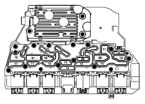
Fig. 28: Control Solenoid (w/Body and TCM) Valve Assembly -- Channel Plate Side

Control Solenoid (w/Body and TCM) Valve Assembly - Channel Plate Side

    READ NEXT:

     Specifications

    FASTENER TIGHTENING SPECIFICATIONS (ON VEHICLE) Fastener Tightening Specifications (On Vehicle) FASTENER TIGHTENING SPECIFICATIONS (OFF VEHICLE) Fastener Tightening Specifications (Off Vehicle)

     Manual Transmission - M20 M32 (MR5)

    SPECIFICATIONS FASTENER TIGHTENING SPECIFICATIONS Fastener Tightening Specifications MANUAL TRANSMISSION SPECIFICATIONS Manual Transmission Specifications Schematic wiring diagrams MANUAL TRANSM

     Component locator

    MANUAL TRANSMISSION COMPONENT VIEWS Shift Control and Shift Lever/Selector Lever Cable Components Fig. 3: Shift Control and Shift Lever/Selector Lever Cable Components Shift Shaft Components Fig

    SEE MORE:

     Diagnostic information and procedures

    SCHEMATIC WIRING DIAGRAMS HVAC WIRING SCHEMATICS (ENCORE) Power, Ground, and Blower Motor Fig. 1: Power, Ground, and Blower Motor Compressor Controls Fig. 2: Compressor Controls Duct and Evaporator Temperature Sensors Fig. 3: Duct and Evaporator Temperature Sensors Mode and Temperature Control

     DTC B3125, B3130, OR B3135: Driver door only unlock/all doors lock/unlock

    Diagnostic Instructions Perform the Diagnostic System Check - Vehicle prior to using this diagnostic procedure. Review Strategy Based Diagnosis for an overview of the diagnostic approach. Diagnostic Procedure Instructions provides an overview of each diagnostic category. DTC Descriptors D

    © 2019-2024 Copyright www.chevtrax.com