Chevrolet Trax: DTC B1925 OR B2170 (without memory A45): Seat cushion heater sensor
SCHEMATIC WIRING DIAGRAMS
HEATED/COOLED SEAT WIRING SCHEMATICS (ENCORE)
KA1
Fig. 1: KA1
HEATED/COOLED SEAT WIRING SCHEMATICS (TRAX)
KA1
Fig. 2: KA1
DIAGNOSTIC INFORMATION AND PROCEDURES
DTC B1925 OR B2170 (WITHOUT MEMORY A45): SEAT CUSHION HEATER SENSOR
DIAGNOSTIC CODE INDEX
Diagnostic Instructions
- Perform the Diagnostic System Check - Vehicle prior to using this diagnostic procedure.
- Review Strategy Based Diagnosis for an overview of the diagnostic approach.
- Diagnostic Procedure Instructions provides an overview of each diagnostic category.
DTC Descriptors
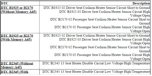
DTC B1925 02
Driver Seat Cushion Heater Sensor Circuit Short to Ground
DTC B1925 05
Driver Seat Cushion Heater Sensor Circuit High Voltage/Open
DTC B2170 02
Passenger Seat Cushion Heater Sensor Circuit Short to Ground
DTC B2170 05
Passenger Seat Cushion Heater Sensor Circuit High Voltage/Open
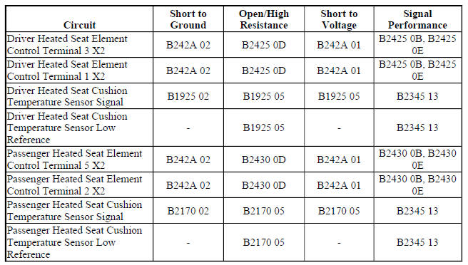
Diagnostic Fault Information
Circuit/System Description
The heated seat temperature sensor is located in the seat cushion just under the seat cover with the seat heating element. The seat heating control module supplies a 5 V reference voltage through the temperature sensor signal circuit and a ground through the low reference circuit to the sensor. The module monitors the voltage of the sensor signal circuit to determine the temperature of the seat. The temperature sensor varies in resistance based on the temperature of the heating element causing the signal voltage to change. Once the seat reaches the set temperature, the module will then cycle the control circuit of the heating elements ON and OFF in order to maintain the desired seat temperature based on the feedback voltage from the sensor.
Conditions for Running the DTC
- DTC B1325 must not be present.
- The seat heating control module must be powered.
Conditions for Setting the DTC
B1925 02 or B2170 02
The temperature sensor voltage drops below 0.6 V for more than 1 s.
B1925 05 or B2170 05
The temperature sensor voltage is greater than 5 V for more than 1 s.
Action Taken When the DTC Sets
The heated seat function for the affected seat will be disabled.
Conditions for Clearing the DTC
- The current DTC will clear and set the code to history 3 s after the reference voltage returns to normal operating range and the ignition is cycled OFF then back to ACC or RUN.
- The history DTC will clear after 40 consecutive fault-free ignition cycles have occurred.
Reference Information
Schematic Reference
Heated/Cooled Seat Schematics (Encore), Heated/Cooled Seat Schematics (Trax)
Connector End View Reference
WIRING SYSTEMS AND POWER MANAGEMENT - COMPONENT CONNECTOR END VIEWS - INDEX - ENCORE WIRING SYSTEMS AND POWER MANAGEMENT - COMPONENT CONNECTOR END VIEWS - INDEX - TRAX
Description and Operation
Heated Seats Description and Operation
Electrical Information Reference
- Circuit Testing
- Connector Repairs
- Testing for Intermittent Conditions and Poor Connections
- Wiring Repairs
Scan Tool Reference
Control Module References for scan tool information
Circuit/System Testing
- Ignition OFF and all vehicle systems OFF, disconnect the harness connector at the appropriate E14 Seat Heating Element - Cushion. It may take up to 2 min for all vehicle systems to power down.
- Test for less than 10 ohms between the low reference circuit terminal C and ground.
- If 10 ohms or greater
- Ignition OFF, disconnect the X2 harness connector at the K29 Seat Heating Control Module.
- Test for less than 2 ohms in the low reference circuit end to end.
- If 2 ohms or greater, repair the open/high resistance in the circuit.
- If less than 2 ohms, replace the K29 Seat Heating Control Module.
- If less than 10 ohms
- Ignition ON.
- Test for 4.8-5.2 V between the signal circuit terminal B and ground.
- If less than 4.8 V
- Ignition OFF, disconnect the X3 harness connector at the K29 Seat Heating Control Module.
- Test for infinite resistance between the signal circuit and ground.
- If less than infinite resistance, repair the short to ground on the circuit.
- If infinite resistance
- Test for less than 2 ohms in the signal circuit end to end.
- If 2 ohms or greater, repair the open/high resistance in the circuit.
- If less than 2 ohms, replace the K29 Seat Heating Control Module.
- If greater than 5.2 V
- Ignition OFF, disconnect the X3 harness connector at the K29 Seat Heating Control Module, ignition ON.
- Test for less than 1 V between the signal circuit and ground.
- If 1 V or greater, repair the short to voltage on the circuit.
- If less than 1 V, replace the K29 Seat Heating Control Module.
- If between 4.8-5.2 V
- Test or replace the E14 Seat Heating Element - Cushion.
Component Testing
Seat Cushion Heating Element
- Ignition OFF, disconnect the harness connector at the appropriate E14 Seat Heating Element - Cushion.
- Test for 500 ohms-300 kohms between the signal circuit terminal B and the low reference circuit terminal C.
- If not between 500 ohms-300 kohms
Replace the E14 Seat Heating Element - Cushion.
- If between 500 ohms-300 kohms
- All OK.
Repair Instructions
Perform the Diagnostic Repair Verification after completing the repair.
- Driver or Passenger Seat Cushion Heater Replacement
- Control Module References for K29 Seat Heating Control Module replacement, programming and setup
