Chevrolet Trax: Security indicator malfunction
Diagnostic Instructions
- Perform the Diagnostic System Check - Vehicle prior to using this diagnostic procedure.
- Review Strategy Based Diagnosis for an overview of the diagnostic approach.
- Diagnostic Procedure Instructions provides an overview of each diagnostic category.
Diagnostic Fault Information
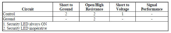
Circuit/System Description
The security LED is controlled by the Body Control Module (BCM) based on commands from the content theft deterrent system. The security LED is located in the instrument panel as part of the ambient light sensor and is supplied ground at all times. When the content theft deterrent system requests the LED be illuminated, the BCM applies voltage to the control circuit, illuminating the LED.
Reference Information
Schematic Reference
Theft Deterrent System Schematics (Encore), Theft Deterrent System Schematics (Trax)
Connector End View Reference
WIRING SYSTEMS AND POWER MANAGEMENT - COMPONENT CONNECTOR END VIEWS - INDEX - ENCORE WIRING SYSTEMS AND POWER MANAGEMENT - COMPONENT CONNECTOR END VIEWS - INDEX - TRAX
Description and Operation
Theft Systems Description and Operation
Electrical Information Reference
- Circuit Testing
- Connector Repairs
- Testing for Intermittent Conditions and Poor Connections
- Wiring Repairs
Scan Tool Reference
Control Module References for scan tool information
Circuit/System Verification
- Arm the content theft deterrent system.
- Verify the security LED illuminates or flashes during the arming sequence.
If the security LED does not illuminate or flash
Refer to Circuit/System Testing
If the security LED illuminates or flashes
- All OK.
Circuit/System Testing
- Ignition OFF and all vehicle systems OFF, disconnect the harness
connector at the B104 Sunload Sensor.
It may take up to 2 minutes for all vehicle systems to power down.
- Test for less than 30 ohms between the ground circuit terminal 6 and ground.
If 30 ohms or greater
- Ignition OFF.
- Test for less than 2 ohms in the ground circuit end to end.
- If 2 ohms or greater, repair the open/high resistance in the circuit.
- If less than 2 ohms, repair the open/high resistance in the ground connection.
If less than 30 ohms
- Ignition ON, connect a test lamp between the control circuit terminal 1 and the ground circuit terminal 6.
- Verify the test lamp turns ON and OFF when commanding the Security Indicator On and Off with a scan tool.
If the test lamp is always OFF
- Ignition OFF, disconnect the harness connector at the K9 Body Control Module.
- Test for infinite resistance between the control circuit and ground.
- If less than infinite resistance, repair the short to ground on the circuit.
- If infinite resistance
- Test for less than 2 ohms in the control circuit end to end.
- If 2 ohms or greater, repair the open/high resistance in the circuit.
- If less than 2 ohms, replace the K9 Body Control Module.
If the test lamp is always ON
- Ignition OFF, disconnect the harness connector at the K9 Body Control Module, ignition ON.
- Test for less than 1 V between the control circuit and ground.
- If 1 V or greater, repair the short to voltage on the circuit.
- If less than 1 V, replace the K9 Body Control Module.
If the test lamp turns ON and OFF
- Test or replace the B104 Sunload Sensor.
Repair Instructions
Perform the Diagnostic Repair Verification after completing the repair.
- Sun Load Temperature Sensor Replacement
- Control Module References for Body Control Module replacement, programming, and setup
READ NEXT:
 Theft Deterrent - Description and operation
THEFT SYSTEMS DESCRIPTION AND OPERATION
When armed, the content theft deterrent system is designed to deter vehicle
content theft by pulsing the horns
and exterior lamps for approximately 30 seconds
Bumpers and Fascias
Repair instructions
SPECIFICATIONS
FASTENER TIGHTENING SPECIFICATIONS
Fastener Tightening Specifications
REPAIR INSTRUCTIONS
FRONT BUMPER FASCIA ENERGY UPPER ABSORBER REPLACEMENT
Fig. 1: Front Bum
Cruise Control
Schematic wiring diagrams
Cruise control system wiring schematics (ENCORE)
Cruise Control
Fig. 1: Cruise Control System Wiring Schematic
CRUISE CONTROL SYSTEM WIRING SCHEMATICS (TRAX)
Cruise Control
SEE MORE:
Making a Call Using
Phone Book
For cell phones that support the
phone book feature, the Bluetooth
system can use the contacts stored
on your cell phone to make calls.
See your cell phone's owner's guide
or contact your wireless provider to
find out if this feature is supported
by your phone.
When a cell phone supports the
phone
Roof Rack System
Warning
If something is carried on top of
the vehicle that is longer or wider
than the roof rack-like paneling,
plywood, or a mattress-the
wind can catch it while the vehicle
is being driven. The item being
carried could be violently torn off,
and this could cause a collision
and damage the vehicle.
