Chevrolet Trax: Control solenoid valve and transmission control module assembly input Shaft speed/output shaft speed input test
Special Tools
- EL 35616 GM-Approved Terminal Test Kit
- EL 38522 Variable Signal Generator
For equivalent regional tools, refer to Special Tools .
.gif)
Fig. 2: View Of Special Tool & Control Solenoid Valve and Transmission
Control Module Assembly
The purpose of this test is to provide a simulated input/output speed sensor (ISS/OSS) signal to the control solenoid valve assembly ISS/OSS input circuits.
Transmission Input Speed Sensor
- Ignition OFF, disconnect the ISS wiring harness connector X3 (1) from the control solenoid valve assembly.
- Ignition ON, test for 11-14 volts at terminal B.
- If not within the specified range, replace the control solenoid valve assembly. Refer to Control Solenoid Valve and Transmission Control Module Assembly Replacement
- Ignition OFF, using the EL 35616 terminal test kit , connect the EL 38522 variable signal generator red lead to the ISS signal circuit terminal A on the TCM.
- Connect the black lead from the EL 38522 variable signal generator to ground.
- Set the EL 38522 variable signal generator to 5 volts, the frequency to 300 Hz, and the percent duty cycle to 50 or the normal position.
- Ignition ON, verify with a scan tool the Transmission ISS parameter is between 495-505 RPM.
- If not within the specified range, replace the control solenoid valve assembly. Refer to Control Solenoid Valve and Transmission Control Module Assembly Replacement .
Transmission Output Speed Sensor
- Ignition OFF, disconnect the OSS wiring harness connector X4 (2) from the control solenoid valve assembly.
- Ignition ON, test for 11-14 volts at terminal B.
- If not within the specified range, replace the control solenoid valve assembly. Refer to Control Solenoid Valve and Transmission Control Module Assembly Replacement .
- Ignition OFF, using the EL 35616 terminal test kit , connect the EL 38522 variable signal generator red lead to the OSS signal circuit terminal A on the TCM.
- Connect the black lead from the EL 38522 variable signal generator to ground.
- Set the EL 38522 variable signal generator to 5 volts, the frequency to 300 Hz, and the percent duty cycle to 50 or the normal position.
- Ignition ON, verify with a scan tool the Transmission OSS parameter is between 745-825 RPM.
- If not within the specified range, replace the control solenoid valve assembly. Refer to Control Solenoid Valve and Transmission Control Module Assembly Replacement
CONTROL SOLENOID VALVE AND TRANSMISSION CONTROL MODULE ASSEMBLY SOLENOID PERFORMANCE TEST
Special Tools
DT-48616 Solenoid Assembly Test Kit & Adapter Harness
For equivalent regional tools, refer to Special Tools .
Fig. 3: Identifying Control Solenoid (W/Body & TCM) Valve Assembly Test
Points
NOTE: Air inlet may be installed at either end of the DT-48616-1 test plate.
The purpose of this procedure is to test the functionality of the control solenoid valve assembly solenoids for a gross stuck open or stuck closed condition. The DT-48616-1 test plate is bolted to the control solenoid valve assembly on the valve body mounting surface. Pressurized air is passed into the aluminum test block, through the control solenoid valve assembly solenoid passage and back to a pressure gauge on the test block. The pressure gauge indicates open if air pressure is passed through the solenoid, or closed if the solenoid is unable to pass air through. A scan tool is used to command the solenoids ON and OFF. While watching the pressure gauge, one can determine the valve functionality.
NOTE: The scan tool output control will not work on Gen 1 transmissions, thus the Q8 Control Solenoid Valve Assembly performance test cannot be performed on these models. Gen 2 and later transmissions do not contain transmission fluid pressure switches. As a result, Gen 2 and later transmissions cannot have a valid Transmission Fluid Pressure Switch DTC. Steps 1 and 2 in the test procedure will determine if you are working with a Gen 1 or Gen 2 and later transmission.
- Ignition ON, use a scan tool to check for Specific DTC P0842.
- Verify that DTC P0842 shows Invalid or a blank screen.
If scan tool does not show Invalid or a blank form
- Do not attempt to complete the performance test as it will not work on a Gen 1 Q8 Control Solenoid Valve Assembly.
- Verify the vehicle model year, engine, and options to make certain the correct diagnostic is selected.
If scan tool shows Invalid or a blank form
- Remove the Q8 Control Solenoid Valve Assembly and filter plate from the transmission. Refer to Control Solenoid Valve and Transmission Control Module Assembly Replacement .
CAUTION: Refer to Fastener Caution .
NOTE: Drain the TCM of excess transmission fluid before attaching to test block and use caution when attaching air to test block air inlet.
- Bolt the DT-48616-1 test plate to the filter plate, and Q8 Control Solenoid Valve Assembly. Use the bolts and washers supplied with the tool to attach the test block. Tighten the bolts to 5 N.m (44 lb in) using a center out alternating torque sequence.
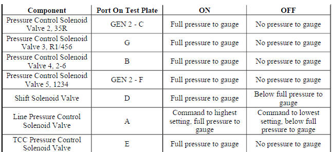
- Install the pressure gauge to the affected solenoid air port. Reference the Control Solenoid Valve Assembly Solenoid Performance Test Plate to Component Identification for test plate port identification.
NOTE: If air pressure greater than 345 kpa (50 psi) is applied, an accurate test of the shift solenoid cannot be performed.
- Regulate the shop air pressure to 310-345 kpa (45-50 psi) and connect the line to the DT-48616-1 test plate air inlet port.
- Connect the DT-48616-10 harness to the vehicle harness and the Q8 Control Solenoid Valve Assembly.
Fig. 4: Valve Pressure Test
NOTE: The TCM limits the time the solenoids are commanded on to prevent overheating of the solenoids. Once the time limit is reached, the TCM prevents the test from being continued for 5 min. The ignition must remain ON during the 5 min countdown period.
- Ignition ON.
NOTE:
- Release the air pressure in the gauge between pressurization tests.
- If the solenoid valve is stuck, no pressure change will occur.
- Verify the pressure gauge changes when commanding the appropriate solenoid ON and OFF with a scan tool. Repeat test as necessary.
If the pressure gauge does not change
Replace the Q8 Control Solenoid Valve Assembly.
If the pressure gauge changes
- Solenoids are not grossly stuck.
Control Solenoid Valve Assembly Solenoid Performance Test Plate to Component Identification
NOTE: With the key on engine off, the TCM will normally cycle some of the transmission solenoids On and Off to facilitate keeping the ports and solenoids clean and free of debris. This dither function is a normal activity and will cause the valves to cycle open and closed quickly when the TCM is powered up. This can cause the psi gauge to flicker high and low as the valves open and close. This may cause some air to exit the ports where the psi gauge is not connected as those solenoids cycle on and off.
READ NEXT:
 Transmission adaptive values learn
Transmission Adaptive Values Learn is a procedure for 6 speed automatic
transmissions in which a series of
tests are run to allow the transmission control module (TCM) to learn individual
clutch cha
Transmission fluid level and condition check
This procedure checks both the transmission fluid level, as well as the
condition of the fluid itself.
CAUTION: Use Dexron VI transmission fluid only. Failure to use the
proper fluid
may result in t
Line pressure check
Special Tools
GE-21867-A Oil Pressure Gauge Kit
For equivalent regional tools, refer to Special Tools .
Fig. 6: Illustrating Line Pressure Checking
WARNING: Keep the brakes applied at all times in o
SEE MORE:
DTC B370A: Rain sensor
DIAGNOSTIC CODE INDEX
DIAGNOSTIC CODE INDEX
DTC B370A: RAIN SENSOR
Diagnostic Instructions
Perform the Diagnostic System Check - Vehicle prior to using this
diagnostic procedure.
Review Strategy Based Diagnosis for an overview of the diagnostic
approach.
Diagnostic Procedure Instructions
Descent Control System (DCS)
If equipped, the DCS allows the
vehicle to travel at a low speed
without applying the brake.
The vehicle will automatically
decelerate to a low speed and
remain there when DCS is
turned on.
Use only when descending steep
grades while driving off-road. Do not
use when driving on normal road
surfaces
