Chevrolet Trax: Symptoms - automatic transmission
NOTE: Use the symptom tables only if the following conditions are met:
- Refer to Diagnostic Starting Point - Vehicle .
- There are no DTCs set.
- The control modules can communicate via the serial data link.
- Review the system operation in order to familiarize yourself with the system functions. Refer to Transmission General Description , and Transmission Component and System Description .
Visual/Physical Inspection
Inspect the easily accessible or visible system components for obvious damage or conditions which could cause the symptom.
Intermittent
Faulty electrical connections or wiring may be the cause of intermittent conditions. Refer to Testing for Intermittent Conditions and Poor Connections .
Symptom List
Refer to a symptom diagnostic procedure from the following list in order to diagnose the symptom:
Fluid Diagnosis
- Transmission Fluid Level and Condition Check
- Fluid Pressure High or Low
- Automatic Transmission Fluid Leaks
- Fluid Leak Diagnosis (Non Hybrid)
Noise and Vibration Diagnosis
- Whine/Growl Noise
- Noise and Vibration Analysis
- Torque Converter Diagnosis
- Non-Shifting Clutch Function Verification Description for bump
Range Performance Diagnosis
- No Park
- No Drive in All Ranges
- No Reverse Gear
Shift Quality Feel Diagnosis
- Harsh Garage Shift
- Harsh or Late First, Second, Third, and Fourth Shift
- Harsh First and Reverse Shift
- Harsh or Late Second and Sixth Shift
- Harsh or Late Third, Fifth, and Reverse Shift
- Harsh Fourth, Fifth, and Sixth Shift
- Non-Shifting Clutch Function Verification Description for bump
Shift Pattern
- No First and Reverse Gears
- No First, Second, Third, and Fourth Gear
- No Second and Sixth Gear
- No Fourth, Fifth, and Sixth Gear
- No Third, Fifth, and Reverse Gear
Torque Converter Diagnosis
- Torque Converter Diagnosis
- No Torque Converter Clutch Apply
- No Torque Converter Clutch Release
Symptom Not Found or No Symptom Detected
- Transmission Fluid Level and Condition Check
- Road Test
- Line Pressure Check
- Non-Shifting Clutch Function Verification Description for bump
CONTROL SOLENOID VALVE AND TRANSMISSION CONTROL MODULE ASSEMBLY INSPECTION

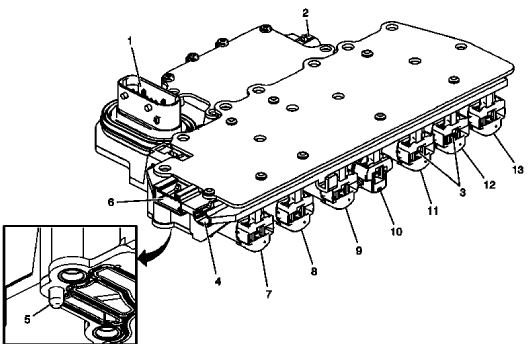
Fig. 1: View Of Control Solenoid Valve & Transmission Control Module Assembly
- Verify the conditions listed below do not exist. Carefully inspect the control solenoid valve assembly connectors and pins (1, 2, 4, 6) for the condition. Repair or replace as necessary.
- Damage
- Bent pins
- Debris
- Broken retaining tab
- Contamination
- Verify there is no metallic debris inside the connectors near the terminal pins. Clean as necessary.
- Verify the control solenoid valve assembly solenoid leads (3) do not have contamination or metallic debris. Clean as necessary.
- Verify the resistance between the leads of each solenoid valve is within the range in the table below, with the solenoid valves at room temperature. If the resistance of any solenoid valve is not within range, replace the Control Valve Body Assembly.
- Inspect the 2 control solenoid valve assembly filter plate retaining tabs (5) for cracks and ensure proper tension when filter plate is attached.
NOTE: The connector on the TCC pressure control solenoid valve (8) will be either clear/transparent or yellow. The clear/transparent connector will have a color contrast when compared to the connectors on pressure control solenoid valve 2 (11) and pressure control solenoid valve 4 (12).
Solenoid Resistance
.jpg)

