Chevrolet Trax: Schematic wiring diagrams
ENGINE CONTROLS WIRING SCHEMATICS (ENCORE)
Module Power, Ground, Serial Data, and MIL
.jpg)
Fig. 1: Module Power, Ground, Serial Data, and MIL
5V1, 5V2, and Low Reference Bus (1 of 2)
.jpg)
Fig. 2: 5V1, 5V2, and Low Reference Bus (1 of 2)
5V3, 5V4, and Low Reference Bus (2 of 2)
.jpg)
Fig. 3: 5V3, 5V4, and Low Reference Bus (2 of 2)
Engine Data Sensors - Pressure, and Temperature
.jpg)
Fig. 4: Engine Data Sensors - Pressure, and Temperature
Camshaft, Crankshaft, and Knock Sensors, Camshaft Actuators
.jpg)
Fig. 5: Camshaft, Crankshaft, and Knock Sensors, Camshaft Actuators
Engine Data Sensors - Throttle and Brake Sensor Controls
.jpg)
Fig. 6: Engine Data Sensors - Throttle and Brake Sensor Controls
Fuel Controls - Fuel Injectors and Ignition Controls
.jpg)
Fig. 7: Fuel Controls - Fuel Injectors and Ignition Controls
Engine Data Sensors - Oxygen Sensors
.jpg)
Fig. 8: Engine Data Sensors - Oxygen Sensors
Fuel Controls - Evaporative Emission and Device Controls
.jpg)
Fig. 9: Fuel Controls - Evaporative Emission and Device Controls
Fuel Controls - Fuel Pump and Fuel Pump Controls (LUV)
.jpg)
Fig. 10: Fuel Controls - Fuel Pump and Fuel Pump Controls (LUV)
Fuel Controls - Fuel Pump (LUJ)
.jpg)
Fig. 11: Fuel Controls - Fuel Pump (LUJ)
Controlled/Monitored Subsystem References
.jpg)
Fig. 12: Controlled/Monitored Subsystem References
ENGINE CONTROLS WIRING SCHEMATICS (TRAX)
Module Power, Ground, Serial Data, and MIL
.jpg)
Fig. 13: Module Power, Ground, Serial Data, and MIL
5V1, 5V2, and Low Reference Bus (1 of 2)
.jpg)
Fig. 14: 5V1, 5V2, and Low Reference Bus (1 of 2)
5V3, 5V4, and Low Reference Bus (2 of 2)
.jpg)
Fig. 15: 5V3, 5V4, and Low Reference Bus (2 of 2)
Engine Data Sensors - Pressure, and Temperature
.jpg)
Fig. 16: Engine Data Sensors - Pressure, and Temperature
Camshaft, Crankshaft, and Knock Sensors, Camshaft Actuators
.jpg)
Fig. 17: Camshaft, Crankshaft, and Knock Sensors, Camshaft Actuators
Engine Data Sensors - Throttle and Brake Sensor Controls
.jpg)
Fig. 18: Engine Data Sensors - Throttle and Brake Sensor Controls
Fuel Controls - Fuel Injectors and Ignition Controls
.jpg)
Fig. 19: Fuel Controls - Fuel Injectors and Ignition Controls
Engine Data Sensors - Oxygen Sensors
.jpg)
Fig. 20: Engine Data Sensors - Oxygen Sensors
Fuel Controls - Evaporative Emission and Device Controls
.jpg)
Fig. 21: Fuel Controls - Evaporative Emission and Device Controls
Fuel Controls - Fuel Pump and Fuel Pump Controls (FHA)
.jpg)
Fig. 22: Fuel Controls - Fuel Pump and Fuel Pump Controls (FHA)
Fuel Controls - Fuel Pump (-FHA)
.jpg)
Fig. 23: Fuel Controls - Fuel Pump (-FHA)
Controlled/Monitored Subsystem References
.jpg)
Fig. 24: Controlled/Monitored Subsystem References
SPECIAL TOOLS AND EQUIPMENT
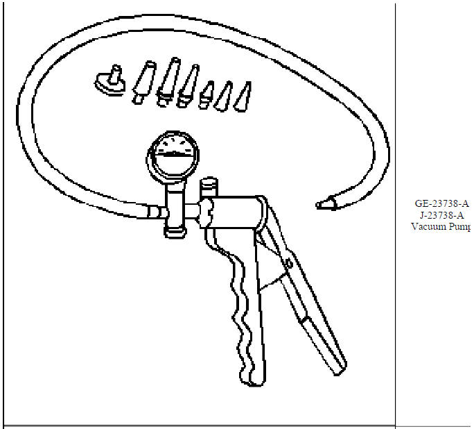
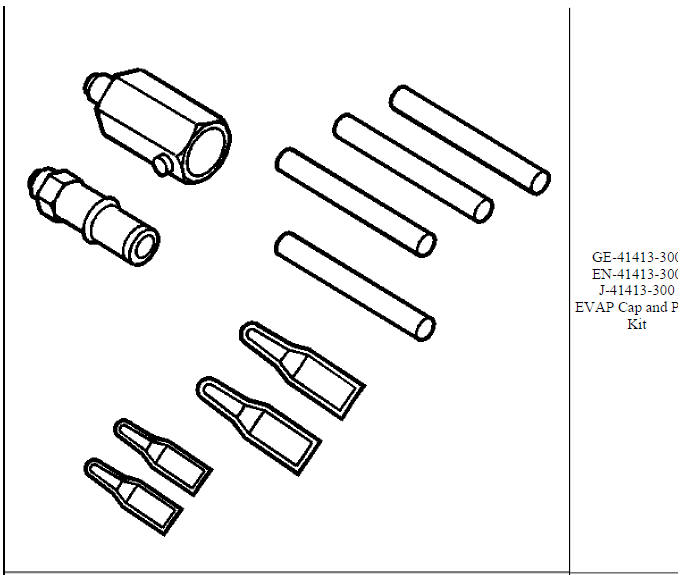
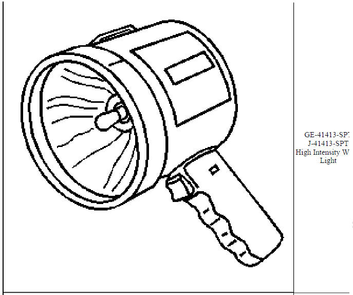
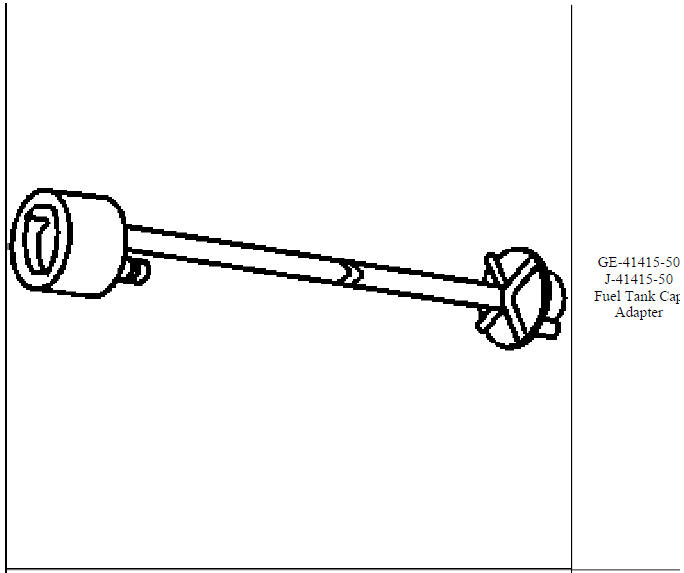
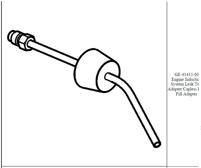
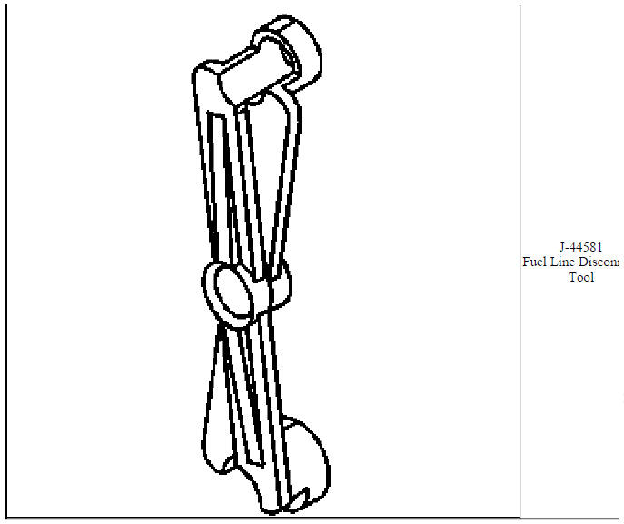
SPECIAL TOOLS (DIAGNOSTIC TOOLS)
.jpg)
.jpg)
.jpg)
.jpg)
.jpg)
.jpg)
.jpg)
.jpg)
.jpg)
.jpg)
.jpg)
.jpg)
.jpg)
.jpg)
.jpg)
.jpg)
.jpg)
.jpg)
.jpg)
.jpg)
.jpg)
.jpg)
.jpg)
.jpg)
.jpg)
.jpg)
.jpg)
.jpg)
.jpg)
.jpg)
.jpg)
.jpg)
.jpg)
.jpg)
.jpg)
.jpg)
.jpg)
.jpg)
.jpg)
.jpg)
.jpg)
SPECIFICATIONS
Temperature Versus Resistance
.jpg)
Temperature Versus Resistance - Intake Air Temperature Sensor (Bosch Sensor)
.jpg)
.jpg)
Temperature Versus Resistance - Intake Air Temperature Sensor (Delco Sensor)
.jpg)
Altitude Versus Barometric Pressure
.jpg)
.jpg)
Ignition System Specifications
.jpg)
Fastener Tightening Specifications
.jpg)
.jpg)
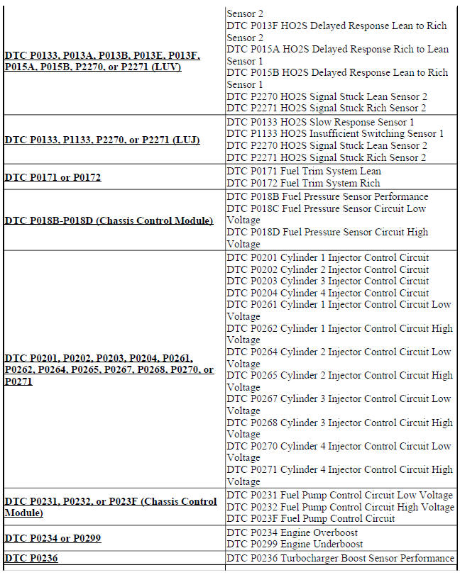
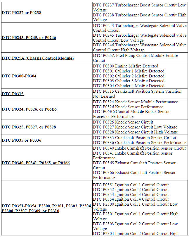
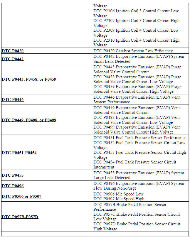
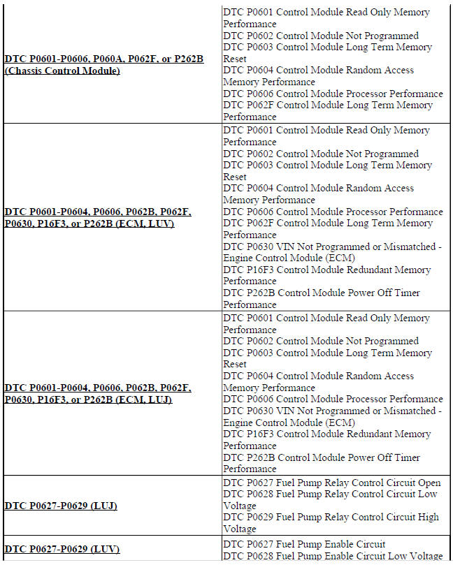
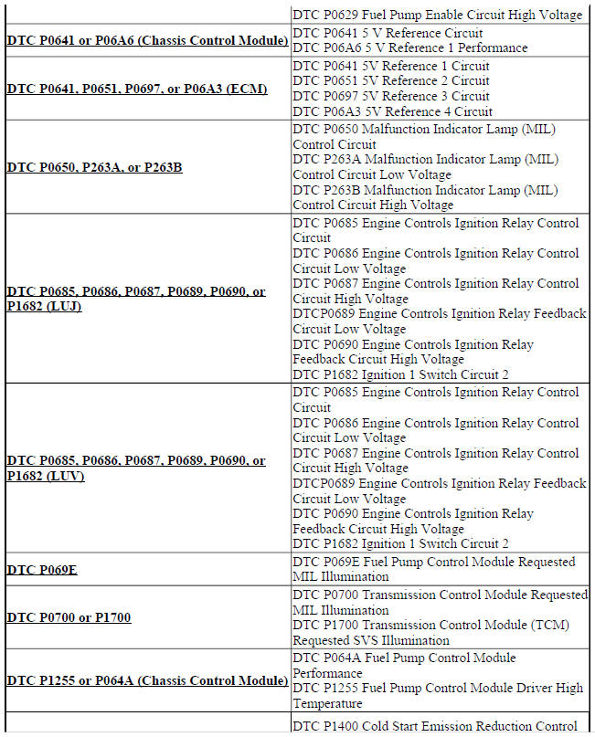
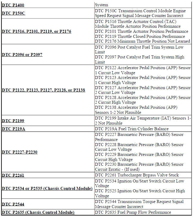
DIAGNOSTIC CODE INDEX
.jpg)
.jpg)
.jpg)
READ NEXT:
 Schematic wiring diagrams
SPECIFICATIONS
TEMPERATURE VERSUS RESISTANCE
Temperature Versus Resistance
Fastener Tightening Specifications
SCHEMATIC WIRING DIAGRAMS
ENGINE HEATING/COOLING WIRING SCHEMATICS (ENCORE)
Engine C
SEE MORE:
Folding the Seatback
Either side of the seatback can be
folded down for more cargo space.
Fold a seatback only when the
vehicle is not moving.
Caution
Folding a rear seat with the safety
belts still fastened may cause
damage to the seat or the safety
belts. Always unbuckle the safety
belts and return them to their
norm
Power steering hose disconnected caution
CAUTION: Do not start the vehicle with any power steering gear inlet or
outlet hoses
disconnected. When disconnected, plug or cap all openings of
components. Failure to do so could result in contamination or loss of
power steering fluid and damage to the system.
REFRIGERANT PRESSURE DURING TESTING
