Chevrolet Trax: Power door child lock malfunction
Diagnostic Instructions
- Perform the Diagnostic System Check - Vehicle prior to using this diagnostic procedure.
- Review Strategy Based Diagnosis for an overview of the diagnostic approach.
- Diagnostic Procedure Instructions provides an overview of each diagnostic category.
Diagnostic Fault Information
.jpg)
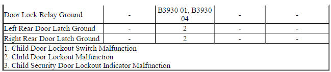
Circuit/System Description
The child door lockout switch on the front floor console controls the child locks on the rear doors. The lockout switch is an input to the body control module which controls the child security lock disable relay. When the body control module detects a voltage drop on the child door lockout signal circuit, it will apply voltage to the child security lock disable relay coil, this will energize the relay and the contact within the relay will then direct the voltage to lock the left rear and right rear child locks and then isolate them from the normal door lock system to prevent the rear doors from being opened by using the interior rear door handles. The body control module will then provide a ground for the lockout indicator causing the indicator to illuminate to notify the driver that the child door lockout system has been activated. If the body control module detects a fault in the child door lockout system, it will command the lockout indicator to flash ON and OFF for 30 seconds.
Reference Information
Schematic Reference
Door Lock/Indicator Schematics (Encore), Door Lock/Indicator Schematics (Trax)
Connector End View Reference
WIRING SYSTEMS AND POWER MANAGEMENT - COMPONENT CONNECTOR END VIEWS - INDEX - ENCORE WIRING SYSTEMS AND POWER MANAGEMENT - COMPONENT CONNECTOR END VIEWS - INDEX - TRAX
Description and Operation
Power Door Locks Description and Operation
Electrical Information Reference
- Testing for Intermittent Conditions and Poor Connections
- Circuit Testing
- Wiring Repairs
- Connector Repairs
Scan Tool Reference
Control Module References for scan tool information
Circuit/System Verification
- Ignition ON.
- Verify both interior rear door handles do not open the rear doors when commanding the Child Security Lock Motors ON with a scan tool.
- If both interior rear door handles open the rear doors
Refer to Circuit/System Testing - Security Lockout Inoperative.
- If a single interior rear door handle opens the rear door
Refer to Circuit/System Testing - Single Door Security Lockout Malfunction.
- If both interior door handles do not open the rear doors
- Verify both interior rear door handles will open the rear doors when commanding the Child Security Lock Motors OFF with a scan tool.
- If both interior rear door handles do not open the rear doors
Refer to Circuit/System Testing - Security Lockout Inoperative.
- If a single interior rear door handle does not open the rear door
Refer to Circuit/System Testing - Single Door Security Lockout Malfunction
- If both interior door handles open the rear doors
- Verify the scan tool Left Right Rear Child Security Lock Switch and Right Rear Child Security Lock Switch parameters changes from Inactive to Active when pressing the child lockout switch.
- If the parameters do not change
Refer to Circuit/System Testing - Lockout Switch Inoperative.
- If the parameters changes
- Verify the child lockout indicator turns ON and OFF when pressing the child lockout switch.
- If the child lockout indicator is always ON or always OFF
Refer to Circuit/System Testing - Lockout Indicator Malfunction.
- If the child lockout indicator turns ON and turns OFF
- All OK.
Circuit/System Testing
Security Lockout Inoperative
- Ignition OFF and all vehicle systems OFF, disconnect the X2 harness connector at the X50A Fuse Block- Underhood. It may take up to 2 minutes for all vehicle systems to power down.
- Test for less than 10 ohms between the ground circuit terminal C5 and ground.
- If 10 ohms or greater
- Ignition OFF.
- Test for less than 2 ohms in the ground circuit end to end.
- If 2 ohms or greater, repair the open/high resistance in the circuit.
- If less than 2 ohms, repair the open/high resistance in the ground connection.
- If less than 10 ohms
- Ignition OFF, connect the X2 harness connector at the X50A Fuse Block-Underhood. Disconnect the X4 harness connector at the K9 Body Control Module, ignition ON.
- Verify that a test lamp does not illuminate between the control circuit terminal 8 and ground.
- If the test lamp illuminates
- Ignition OFF, disconnect the X2 harness connector at the X50A Fuse Block-Underhood.
- Test for less than 1 V between the K9 Body Control Module control circuit terminal 8 X4 and ground
- If 1 V or greater, repair the short to voltage on the circuit.
- If less than 1 V, replace the X50A Fuse Block-Underhood.
- If the test lamp is not illuminated
- Connect a 3A fused jumper wire between the control circuit terminal 8 and B+.
- Listen for an audible click from the X50A Fuse Block-Underhood as the KR113 Child Security Lock Disable Relay activates.
- If the KR113 Child Security Lock Disable Relay does not activate
- Ignition OFF, remove the jumper wire, disconnect the X2 harness connector at the X50A Fuse Block-Underhood.
- Test for infinite resistance between the K9 Body Control Module control circuit terminal 8 X4 and ground.
- If less than Infinite resistance, repair the short to ground on the circuit.
- If infinite resistance
- Test for less than 2 ohms in the control circuit end to end.
- If 2 ohms or greater, repair the open/high resistance in the circuit.
- If less than 2 ohms, replace the X50A Fuse Block-Underhood.
- If the KR113 Child Security Lock Disable Relay activates
- Replace the K9 Body Control Module.
Single Door Security Lockout Malfunction
- Ignition OFF, disconnect the harness connector at the appropriate A23 Door Latch Assembly-Rear. Ignition ON.
- Verify the scan tool Rear Child Security Lock Switch parameter is Inactive.
- If not Inactive
- Ignition OFF, disconnect the harness connector at the K9 Body Control Module.
- Test for infinite resistance between the signal circuit terminal listed below and ground:
- A23LR Door Latch Assembly-Left Rear - signal circuit terminal 9
- A23RR Door Latch Assembly-Right Rear - signal circuit terminal 4
- If less than infinite resistance, repair the short to ground on the circuit.
- If infinite resistance, replace the K9 Body Control Module.
- If Inactive
- Install a 3 A fused jumper wire between the signal circuit terminals listed below and ground:
- A23LR Door Latch Assembly-Left Rear - signal circuit terminal 9
- A23RR Door Latch Assembly-Right Rear - signal circuit terminal 4
- Verify the scan tool Rear Child Security Lock Switch parameter is Active.
- If not Active
- Ignition OFF, remove the 3 A fused jumper wire, disconnect the harness connector at the K9 Body Control Module, ignition ON.
- Test for less than 1 V between the signal circuit and ground.
- If 1 V or greater, repair the short to voltage on the circuit.
- If less than 1 V
- Test for less than 2 ohms in the signal circuit end to end.
- If 2 ohms or greater, repair the open/high resistance in the circuit.
- If less than 2 ohms, replace the K9 Body Control Module.
- If Active
- Connect a test lamp between control circuit terminals listed below:
- A23LR Door Latch Assembly-Left Rear - control circuit terminal 4 and control circuit terminal 7
- A23RR Door Latch Assembly-Right Rear - control circuit terminal 2 and control circuit terminal 9
- Verify the test lamp turns ON and OFF when commanding the Child Security Lock Motors Active and Inactive with a scan tool.
- If the test lamp remains OFF during either of the commands
- Ignition OFF, remove the test lamp, disconnect the harness connector at the K9 Body Control Module.
- Test for infinite resistance between each control circuit and ground.
- If less than infinite resistance, repair the short to ground on the circuit.
- If infinite resistance, replace the K9 Body Control Module.
- If the test lamp turns ON during each of the commands
- Test or replace the A23 Door Latch Assembly-Rear.
Lockout Switch Inoperative
- Ignition OFF and all vehicle systems OFF, disconnect the harness connector at the S48E Multifunction Switch-Center Console. It may take up to 2 minutes for all vehicle systems to power down.
- Test for less than 10 ohms between the ground circuit terminal 9 and ground.
- If 10 ohms or greater
- Ignition OFF.
- Test for less than 2 ohms in the ground circuit end to end.
- If 2 ohms or greater, repair the open/high resistance in the circuit.
- If less than 2 ohms, repair the open/high resistance in the ground connection.
- If less than 10 ohms
- Ignition ON.
- Test for greater than 10 V between the signal circuit terminal 3 and ground.
- If 10 V or less
- Ignition OFF, disconnect the harness connector at the K9 Body Control Module.
- Test for infinite resistance between the signal circuit and ground.
- If less than infinite resistance, repair the short to ground on the circuit.
- Test for less than 2 ohms in the signal circuit end to end.
- If 2 ohms or greater, repair the open/high resistance in the circuit.
- If less than 2 ohms, replace the K9 Body Control Module.
- If greater than 10 V
- Test or replace the S48E Multifunction Switch-Center Console.
Lockout Indicator Malfunction
- Ignition OFF, disconnect the harness connector at the S48E Multifunction
Switch-Center Console.
Ignition ON
- Verify a test lamp illuminates between the control circuit terminal 8 and ground.
- If the test lamp does not illuminate
- Ignition OFF, remove the test lamp, disconnect the harness connector at the K9 Body Control Module.
- Test for infinite resistance between the control circuit and ground.
- If less than infinite resistance, repair the short to ground on the circuit.
- If infinite resistance
- Test for less than 2 ohms in the control circuit end to end.
- If 2 ohms or greater, repair the open/high resistance in the circuit.
- If less than 2 ohms, replace the K9 Body Control Module.
- If the test lamp illuminates
- Connect a test lamp between the control circuit terminal 2 and B+ and install a 3A fused at the signal circuit terminal 3.
- Verify the test lamp turns ON and OFF each time the 3A fused jumper wire is connected to ground.
- If the test lamp is always OFF
- Ignition OFF, remove the test lamp, disconnect the harness connector at the K9 Body Control Module, ignition ON.
- Test for less than 1 V between the control circuit and ground.
- If 1 V or greater, repair the short to voltage on the circuit.
- If less than 1 V
- Ignition OFF.
- Test for less than 2 ohms in the control circuit end to end.
- If 2 ohms or greater, repair the open/high resistance in the circuit.
- If less than 2 ohms, replace the K9 Body Control Module.
- If the test lamp is always ON
- Ignition OFF, remove the test lamp, disconnect the harness connector at the K9 Body Control Module.
- Test for infinite resistance between the control circuit and ground.
- If less than infinite resistance, repair the short to ground on the circuit.
- If infinite resistance, replace the K9 Body Control Module.
- If the test lamp turns ON and OFF
- Test or replace the S48E Multifunction Switch-Center Console.
Component Testing
Child Security Lockout Switch Test
- Ignition OFF, disconnect the harness connector at the S48E Multifunction Switch-Center Console.
- Test for infinite resistance between the signal terminal 3 and the ground terminal 9 with the switch in the open position.
- If less than infinite resistance
Replace the S48E Multifunction Switch-Center Console.
- If infinite resistance
- Test for less than 3ohms between the signal terminal 3 and the ground terminal 9 with the switch in the closed position.
- If 3 ohms or greater
Replace the S48E Multifunction Switch-Center Console.
- If less than 3 ohms
- All OK
Door Latch Test
- Ignition OFF, disconnect the harness connector at the appropriate A23 Door Latch Assembly-Rear.
- Install a 30 A fused jumper wire between one of the control terminals and 12 V. Momentarily install a jumper wire between the other control terminal and ground. Reverse the jumper wires at least two times, the A23 Door Latch Assembly-Rear should perform the LOCK and UNLOCK functions.
- If the function does not perform the LOCK and UNLOCK function
Replace the A23 Door Latch Assembly-Rear.
- If the function performs the LOCK and UNLOCK function
- All OK
Repair Instructions
Perform the Diagnostic Repair Verification after completing the repair.
- Rear Side Door Latch Replacement
- Instrument Panel Multifunction Switch Replacement (Encore)
- Front Compartment Fuse Block Replacement
- Control Module References body control module replacement, programming and setup
READ NEXT:
 Power door locks malfunction
Diagnostic Instructions
Perform the Diagnostic System Check - Vehicle prior to using this
diagnostic procedure.
Review Strategy Based Diagnosis for an overview of the diagnostic
approach.
Diag
Vehicle access - Repair instructions
FRONT SIDE DOOR INSIDE HANDLE CABLE REPLACEMENT
Fig. 9: Rear Side Door Inside Handle Cable And Cover
Front Side Door Inside Handle Cable Replacement
REAR SIDE DOOR INSIDE HANDLE CABLE REPLACEMENT
SEE MORE:
Repair instructions
AUDIO AMPLIFIER PROGRAMMING AND SETUP
Replace and Program Control Module or Reprogram Control Module
This control module does not require SPS programming or any setup procedures.
BODY CONTROL MODULE PROGRAMMING AND SETUP
NOTE:
DO NOT program a control module unless directed to by a service
proce
DTC B370A: Rain sensor
DIAGNOSTIC CODE INDEX
DIAGNOSTIC CODE INDEX
DTC B370A: RAIN SENSOR
Diagnostic Instructions
Perform the Diagnostic System Check - Vehicle prior to using this
diagnostic procedure.
Review Strategy Based Diagnosis for an overview of the diagnostic
approach.
Diagnostic Procedure Instructions
