Chevrolet Trax: Power door locks malfunction
Diagnostic Instructions
- Perform the Diagnostic System Check - Vehicle prior to using this diagnostic procedure.
- Review Strategy Based Diagnosis for an overview of the diagnostic approach.
- Diagnostic Procedure Instructions provides an overview of each diagnostic category.
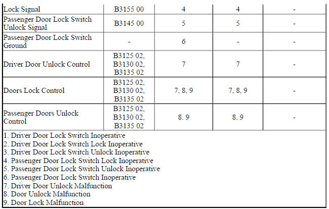
Diagnostic Fault Information
.jpg)
Circuit/System Description
The body control module (BCM) powers the reversible door latch assemblies by providing battery positive voltage and ground to the appropriate lock and unlock control circuits of the door latch assemblies. The lock and unlock control circuits of the rear doors and passenger door latch assemblies are all connected together.
When the door latch assemblies are not active, all actuator lock and unlock control circuits are supplied a floating voltage door driver by the BCM. Transitioning of the lock actuators to the lock or unlocked position depends upon which control circuits receive voltage and which control circuits receive ground.
The BCM supplies a 12 V signal to each of the door lock and door unlock signal circuits. When the door lock switches are in the open position, the voltage level in the signal circuit will be near 12 V. When any door lock switch is pressed to the lock or unlock position, the voltage level in the appropriate signal circuit will drop to 0 V and the BCM will detect the voltage drop and command the door latches to perform the requested lock or unlock command.
The underhood fuse block contains a PCB relay which controls the functions of the electronic child locks which is part of the rear door latch assemblies. When the relay is in it's inactive state and the BCM commands the latches to LOCK and UNLOCK, voltage will pass through the relay contacts for normal LOCK and UNLOCK functions of the passenger, left rear and right rear door latch assemblies
Diagnostic Aids
Verify the smooth and consistent mechanical operation of each part of the door latch system prior to performing extensive electrical diagnostics. Any door that does not function smoothly or consistently, refer to Door Will Not Open/Close, Door Binding, or Locks, Handles, or Cylinders Do Not Function
Reference Information
- Door Lock/Indicator Schematics (Encore), Door Lock/Indicator Schematics (Trax)
- Body Control System Schematics (Encore) , Body Control System Schematics (Trax)
Connector End View Reference
WIRING SYSTEMS AND POWER MANAGEMENT - COMPONENT CONNECTOR END VIEWS - INDEX - ENCORE WIRING SYSTEMS AND POWER MANAGEMENT - COMPONENT CONNECTOR END VIEWS - INDEX - TRAX
Description and Operation
Power Door Locks Description and Operation
Electrical Information Reference
- Circuit Testing
- Connector Repairs
- Testing for Intermittent Conditions and Poor Connections
- Wiring Repairs
Scan Tool Reference
Control Module References for scan tool information
Circuit/System Verification
- Ignition ON.
- Verify the scan tool Driver Door Lock Switch parameter changes from Inactive to Lock and Unlock when pushing the appropriate switch on the S13D Door Lock Switch-Driver.
- If the parameter does not change
Refer to Circuit/System Testing - Driver Door Lock Switch Malfunction.
- If the parameter changes
- Verify the scan tool Passenger Door Lock Switch parameter changes from Inactive to Lock and Unlock when pushing the appropriate switch on the S13P Door Lock Switch-Passenger.
- If the parameter does not change
Refer to Circuit/System Testing - Passenger Door Lock Switch Malfunction
- If the parameter changes
- Verify all vehicle doors LOCK and UNLOCK when commanding the All Doors Lock/Unlock with a scan tool.
- If only the driver door LOCK or UNLOCK functions do not work
Refer to Circuit/System Testing - Driver Door Lock Malfunction
- If one or more, but not all, passenger door LOCK or UNLOCK functions do not work
Refer to Circuit/System Testing - Passenger Door Lock Malfunction.
- If all door LOCK and UNLOCK functions do not work
Refer to Circuit/System Testing - All Door Lock Inoperative.
- If the LOCK and UNLOCK function for all doors works
- Command all doors to UNLOCK with a scan tool.
- Verify all doors to LOCK when pressing the driver door lock plunger down flush with the driver door panel.
- If the door LOCK function for all doors do not work
Refer to Circuit/System Testing - Driver Door Lock Plunger Malfunction.
- If the LOCK function for all doors works
- All OK.
Circuit/System Testing
Driver Door Lock Switch Malfunction
- Ignition OFF and all vehicle systems OFF, disconnect the harness connector at the S13D Door Lock Switch - Driver. It may take up to 2 minutes for all vehicle systems to power down.
- Test for less than 10 ohms between the ground circuit terminal 3 and ground.
- If 10 ohms or greater
- Ignition OFF.
- Test for less than 2 ohms in the ground circuit end to end.
- If 2 ohms or greater, repair the open/high resistance in the circuit.
- If less than 2 ohms, repair the open/high resistance in the ground connection.
- If less than 10 ohms
- Ignition ON.
- Verify the scan tool Driver Door Lock Switch parameter is Inactive.
- If not Inactive
- Ignition OFF, disconnect the harness connector at the K9 Body Control Module.
- Test for infinite resistance between the signal circuit terminal 4 and ground.
- If less than infinite resistance, repair the short to ground on the circuit
- Test for infinite resistance between the signal circuit terminal 2 and ground.
- If less than infinite resistance, repair the short to ground on the circuit.
- If infinite resistance, replace the K9 Body Control Module.
- If Inactive
- Install a 3 A fused jumper wire between the signal circuit terminal 4 and the ground circuit terminal 3.
- Verify the scan tool Driver Door Lock Switch parameter is Lock.
If not Lock
- Ignition OFF, remove the 3 A fused jumper wire, disconnect the harness connector at the K9 Body Control Module, ignition ON.
- Test for less than 1 V between the signal circuit and ground.
- If 1 V or greater, repair the short to voltage on the circuit.
- If less than 1 V
- Test for less than 2 ohms in the signal circuit end to end.
- If 2 ohms or greater, repair the open/high resistance in the circuit.
- If less than 2 ohms, replace the K9 Body Control Module.
- If Lock
- Install a 3 A fused jumper wire between the signal circuit terminal 2 and the ground circuit terminal 3.
- Verify the scan tool Driver Door Lock Switch parameter is Unlock.
- If not Unlock
- Ignition OFF, 3 A fused jumper wire, disconnect the harness connector at the K9 Body Control Module, ignition ON.
- Test for less than 1 V between the signal circuit and ground.
- If 1 V or greater, repair the short to voltage on the circuit.
- If less than 1 V
- Test for less than 2 ohms in the signal circuit end to end.
- If 2 ohms or greater, repair the open/high resistance in the circuit.
- If less than 2 ohms, replace the K9 Body Control Module.
- If Unlock
- Test or replace the S13D Door Lock Switch - Driver
Passenger Door Lock Switch Malfunction
- Ignition OFF and all vehicle systems OFF, disconnect the harness connector at the S13P Door Lock Switch - Passenger. It may take up to 2 minutes for all vehicle systems to power down.
- Test for less than 10 ohms between the ground circuit terminal 3 and ground.
- If 10 ohms or greater
- Ignition OFF.
- Test for less than 2 ohms in the ground circuit end to end.
- If 2 ohms or greater, repair the open/high resistance in the circuit.
- If less than 2 ohms, repair the open/high resistance in the ground connection.
- If less than 10 ohms
- Ignition ON.
- Verify the scan tool Passenger Door Lock Switch parameter is Inactive.
- If not Inactive
- Ignition OFF, disconnect the harness connector at the K9 Body Control Module.
- Test for infinite resistance between the signal circuit terminal 4 and ground.
- If less than infinite resistance, repair the short to ground on the circuit
- Test for infinite resistance between the signal circuit terminal 2 and ground.
- If less than infinite resistance, repair the short to ground on the circuit.
- If infinite resistance, replace the K9 Body Control Module.
- If Inactive
- Install a 3 A fused jumper wire between the signal circuit terminal 4 and the ground circuit terminal 3.
- Verify the scan tool Passenger Door Lock Switch parameter is Lock.
- If not Lock
- Ignition OFF, 3 A fused jumper wire, disconnect the harness connector at the K9 Body Control Module, ignition ON.
- Test for less than 1 V between the signal circuit and ground.
- If 1 V or greater, repair the short to voltage on the circuit.
- If less than 1 V
- Test for less than 2 ohms in the signal circuit end to end.
- If 2 ohms or greater, repair the open/high resistance in the circuit.
- If less than 2 ohms, replace the K9 Body Control Module.
- If Lock
- Install a 3 A fused jumper wire between the signal circuit terminal 2
and the ground circuit terminal 3.
8. Verify the scan tool Passenger Door Lock Switch parameter is Unlock.
- If not Unlock
- Ignition OFF, 3 A fused jumper wire, disconnect the harness connector at the K9 Body Control Module, ignition ON.
- Test for less than 1 V between the signal circuit and ground.
- If 1 V or greater, repair the short to voltage on the circuit.
- If less than 1 V
- Test for less than 2 ohms in the signal circuit end to end.
- If 2 ohms or greater, repair the open/high resistance in the circuit.
- If less than 2 ohms, replace the K9 Body Control Module
If Unlock
- Test or replace the S13P Door Lock Switch - Passenger.
Driver Door Lock Malfunction
- Ignition OFF, disconnect the harness connector at the A23D Door Latch Assembly-Driver. Ignition ON.
NOTE: Leaving the DMM connected between a control circuit and ground for greater than 20 seconds will cause the K9 Body Control Module to interpret the test as a system fault and will cause the voltage on the control circuit to drop to 0 V. If the voltage drops to 0 V, operate the door locks using the door lock switch to restore the voltage for testing.
- Test for greater than 5 V between the control circuit terminal 3 and ground.
- If 5 V or less
- Ignition OFF, disconnect the X6 harness connector at the K9 Body Control Module.
- Test for infinite resistance between the control circuit and ground.
- If less than infinite resistance, repair the short to ground on the circuit.
- If infinite resistance
- Test for less than 2 ohms in the control circuit end to end.
- If 2 ohms or greater, repair the open/high resistance on the circuit.
- If less than 2 ohms, replace the K9 Body Control Module.
- If greater than 5 V
NOTE:
Leaving the DMM connected between a control circuit and ground for greater than 20 seconds will cause the K9 Body Control Module to interpret the test as a system fault and will cause the voltage on the control circuit to drop to 0 V. If the voltage drops to 0 V, operate the door locks using the door lock switch to restore the voltage for testing.
- Test for greater than 5 V between the control circuit terminal 2 and ground.
- If 5 V or less
- Ignition OFF, disconnect the X6 harness connector at the K9 Body Control Module.
- Test for infinite resistance between the control circuit and ground.
- If less than infinite resistance, repair the short to ground on the circuit.
- If infinite resistance
- Test for less than 2 ohms in the control circuit end to end.
- If 2 ohms or greater, repair the open/high resistance on the circuit.
- If less than 2 ohms, replace the K9 Body Control Module.
- If greater than 5 V
- Test or replace the A23D Door Latch Assembly-Driver.
Passenger Door Lock Malfunction
- Ignition OFF, disconnect the harness connector at the appropriate passenger or rear A23 Door Latch Assembly. Ignition ON.
NOTE:
Leaving the DMM connected between a control circuit and ground for greater than 20 seconds will cause the K9 Body Control Module to interpret the test as a system fault and will cause the voltage on the control circuit to drop to 0 V. If the voltage drops to 0 V, operate the door locks using the door lock switch to restore the voltage for testing.
- Test for greater than 5 V between the control circuit terminal listed below and ground:
- A23P Door Latch Assembly-Passenger - control circuit terminal 7
- A23RR Door Latch Assembly-Right Rear - control circuit terminal 7
- A23LR Door Latch Assembly-Left Rear - control circuit terminal 2
- If 5 V or less
- Ignition OFF, disconnect the X6 harness connector at the K9 Body Control Module.
- Test for infinite resistance between the control circuit and ground.
- If less than infinite resistance, repair the short to ground on the circuit.
- If infinite resistance
- Test for less than 2 ohms in the control circuit end to end.
- If 2 ohms or greater, repair the open/high resistance on the circuit.
- If less than 2 ohms, replace the K9 Body Control Module.
- If greater than 5 V
NOTE:
Leaving the DMM connected between a control circuit and ground for greater than 20 seconds will cause the K9 Body Control Module to interpret the test as a system fault and will cause the voltage on the control circuit to drop to 0 V. If the voltage drops to 0 V, operate the door locks using the door lock switch to restore the voltage for testing.
- Test for greater than 5 V between the control circuit terminal listed below and ground:
- A23P Door Latch Assembly-Passenger - control circuit terminal 8
- A23RR Door Latch Assembly-Right Rear - control circuit terminal 8
- A23LR Door Latch Assembly-Left Rear - control circuit terminal 3
- If 5 V or less
- Ignition OFF, disconnect the X2 harness connector at the X50A Fuse Block-Underhood.
- Disconnect the X6 harness connector at the K9 Body Control Module.
- Test for less than 2 ohms between the control circuit terminals listed below:
- X50A Fuse Block-Underhood control circuit terminal B7 X2 and A23P Door Latch Assembly-Passenger control circuit terminal 8
- X50A Fuse Block-Underhood control circuit terminal B4 X2 and K9 Body Control Module control circuit terminal 2 X6
- If greater than 2 ohms, repair the open/high resistance on the circuit.
- Connect the X2 harness connector at the X50A Fuse Block-Underhood
- Test for less than 2 ohms between the A23P Door Latch Assembly-Passenger control circuit terminal 8 and the K9 Body Control Module control circuit terminal 2 X6
- If greater than 2 ohms, replace the X50A Fuse Block-Underhood
- Connect the X6 harness connector at the K9 Body Control Module
- Ignition ON, test for greater than 5 V between the A23P Door Latch Assembly-Passenger control circuit terminal 8 and ground
- If 5 V or less, replace the K9 Body Control Module
- If greater than 5 V
- Test or replace the A23 Door Latch Assembly.
All Door Locks Inoperative
- Ignition OFF, disconnect the X2 harness connector at the K9 Body Control Module, ignition ON.
- Verify a test lamp illuminates between the B+ circuit terminal 4 and ground.
- If the test lamp does not illuminate and the circuit fuse is good
- Ignition OFF.
- Test for less than 2 ohms in the B+ circuit end to end.
- If 2 ohms or greater, repair the open/high resistance in the circuit.
- If less than 2 ohms, verify the fuse is not open and there is voltage at the fuse.
- If the test lamp does not illuminate and the circuit fuse is open
- Ignition OFF.
- Test for infinite resistance between the B+ circuit and ground.
- If less than infinite resistance, repair the short to ground on the circuit.
- If infinite resistance
- Disconnect the harness connector at each A23 Door Latch Assembly.
- Test for infinite resistance between each control circuit and ground.
- If less than infinite resistance, repair the short to ground on the circuit.
- If infinite resistance, replace the appropriate A23 Door Latch Assembly.
- If the test lamp illuminates
- Ignition OFF, connect the X2 harness connector at the K9 Body Control Module. Disconnect the harness connector at the A23D Door Latch Assembly-Driver, ignition ON.
NOTE: Leaving the DMM connected between a control circuit and ground for greater than 20 seconds will cause the K9 Body Control Module to interpret the test as a system fault and will cause the voltage on the control circuit to drop to 0 V. If the voltage drops to 0 V, operate the door locks using the door lock switch to restore the voltage for testing.
- Test for greater than 5 V between the control circuit terminal 2 and ground.
- If 5 V or less
- Ignition OFF, disconnect the X6 harness connector at the K9 Body Control Module.
- Test for infinite resistance between the control circuit terminal listed below and ground:
- Control circuit terminal 1 X6
- Control circuit terminal 2 X6
- Control circuit terminal 4 X6
- If less than infinite resistance, repair the short to ground on the circuit.
- If infinite resistance, replace the K9 Body Control Module.
- If greater than 5 V
- Replace the K9 Body Control Module.
Driver Door Lock Plunger Malfunction
Ignition OFF and all vehicle systems OFF, disconnect the harness connector at the A23D Door Latch Assembly-Driver. It may take up to 2 minutes for all vehicle systems to power down.
Test for less than 10 ohms between the ground circuit terminal 8 and ground.
- If 10 ohms or greater
- Ignition OFF.
- Test for less than 2 ohms in the ground circuit end to end.
- If 2 ohms or greater, repair the open/high resistance in the circuit.
- If less than 2 ohms, repair the open/high resistance in the ground connection.
- If less than 10 ohms
- Ignition ON.
- Test for greater than 10 V between the signal circuit terminal 4 and ground.
- If 10 V or less
- Ignition OFF, disconnect the harness connector at the appropriate component listed below, ignition ON.
- S79D Window Switch-Driver (AER)
- K9 Body Control Module (without AER )
- Test for infinite resistance between the signal circuit and ground.
- If less than infinite resistance, repair the short to ground on the circuit.
- Test for less than 2 ohms in the signal circuit end to end.
- If 2 ohms or greater, repair the open/high resistance in the circuit.
- If less than 2 ohms, replace the K9 Body Control Module or the S79D Window Switch- Driver.
- If greater than 10 V
- Test or replace the A23D Door Latch Assembly-Driver.
Component Testing
Driver Door Lock Switch
- Ignition OFF, disconnect the harness connector at the S13D Door Lock Switch-Driver.
- Test for infinite resistance between the signal terminal 2 and the ground terminal 3 with the switch in the center position.
- If less than infinite resistance
Replace the S13D Door Lock Switch-Driver.
- If infinite resistance
- Test for infinite resistance between the signal terminal 4 and the ground terminal 3 with the switch in the center position
- If less than infinite resistance
Replace the S13D Door Lock Switch-Driver
- If infinite resistance
- Test for less than 2 ohms between the signal terminal 4 and the ground terminal 3 with the switch in the Lock position.
- If 2 ohms or greater
Replace the S13D Door Lock Switch-Driver.
- If less than 2 ohms
- Test for less than 2 ohms between the signal terminal 2 and the ground terminal 3 with the switch in the Unlock position.
- If 2 ohms or greater
Replace the S13D Door Lock Switch-Driver.
- If less than 2 ohms
- All OK
Passenger Door Lock Switch
- Ignition OFF, disconnect the harness connector at the S13P Door Lock Switch-Passenger.
- Test for infinite resistance between the signal terminal 2 and the ground terminal 3 with the switch in the center position.
- If less than infinite resistance
Replace the S13P Door Lock Switch-Passenger
- If infinite resistance
- Test for infinite resistance between the signal terminal 4 and the ground terminal 3 with the switch in the center position.
- If less than infinite resistance
Replace the S13P Door Lock Switch-Passenger
- If infinite resistance
- Test for less than 2 ohms between the signal terminal 4 and the ground terminal 3 with the switch in the Lock position.
- If 2 ohms or greater
Replace the S13P Door Lock Switch-Passenger.
- If less than 2 ohms
- Test for less than 2 ohms between the signal terminal 2 and the ground terminal 3 with the switch in the Unlock position.
- If 2 ohms or greater
Replace the S13P Door Lock Switch-Passenger.
- If less than 2 ohms
- All OK
Door Latch Assembly
- Ignition OFF, disconnect the harness connector at the appropriate A23 Door Latch Assembly.
- Install a 25 A fused jumper wire between one of the control terminals and 12 V. Momentarily install a jumper wire between the other control terminal and ground. Reverse the jumper wires at least two times, the A23 Door Latch Assembly should perform the LOCK and UNLOCK function.
- If the actuator does not perform the LOCK and UNLOCK function
Replace the A23 Door Latch Assembly
- If the actuator performs the LOCK and UNLOCK function
- All OK
Repair Instructions
Perform the Diagnostic Repair Verification after completing the repair.
- Door Lock Switch Replacement - Driver Side (Encore), Door Lock Switch Replacement - Driver Side (Trax)
- Door Lock Switch Replacement - Passenger Front (Encore), Door Lock Switch Replacement - Passenger Front (Trax)
- Rear Side Door Latch Replacement
- Front Side Door Latch Replacement
- Front Compartment Fuse Block Replacement
- Control Module References for body control module replacement, programming and setup
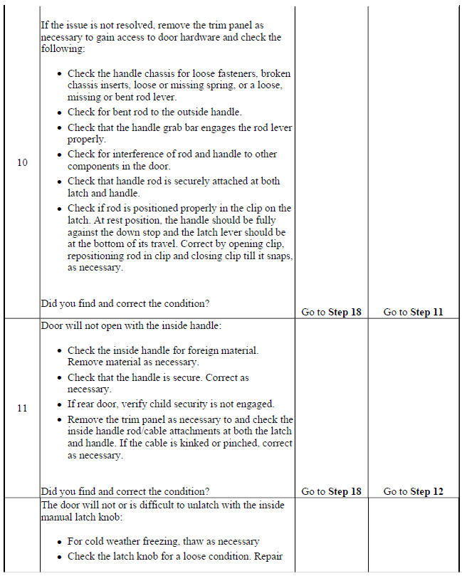
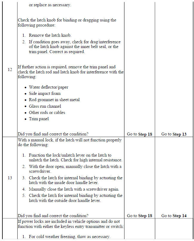
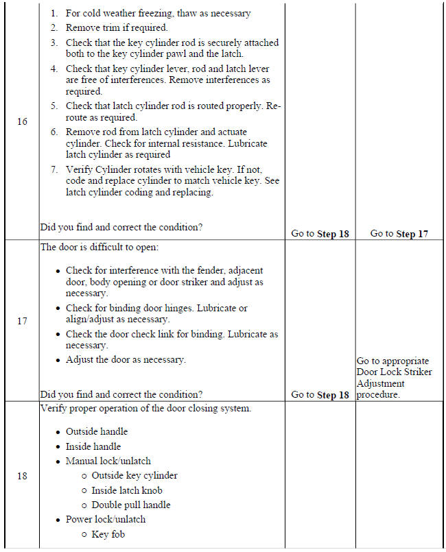
DOOR WILL NOT OPEN/CLOSE, DOOR BINDING, OR LOCKS, HANDLES, OR CYLINDERS DO NOT FUNCTION
Door Will Not Open/Close, Door Binding, or Locks, Handles, or Cylinders Do Not Function
.jpg)
.jpg)
READ NEXT:
 Vehicle access - Repair instructions
FRONT SIDE DOOR INSIDE HANDLE CABLE REPLACEMENT
Fig. 9: Rear Side Door Inside Handle Cable And Cover
Front Side Door Inside Handle Cable Replacement
REAR SIDE DOOR INSIDE HANDLE CABLE REPLACEMENT
Door ajar indicator description and operation
Door Ajar Indicator System Components
The door ajar indicator system consists of the following components:
Body control module
Instrument cluster
Driver door latch
Passenger door latch
Left rear
SEE MORE:
Active Noise Cancellation
SCHEMATIC WIRING DIAGRAMS
ACTIVE NOISE SYSTEM CANCELLATION WIRING SCHEMATICS (ENCORE)
Active Noise Cancellation (NKC)
Fig. 1: Active Noise Cancellation (NKC)
DIAGNOSTIC INFORMATION AND PROCEDURES
ACTIVE NOISE CANCELLATION MALFUNCTION
Diagnostic Instructions
Perform the Diagnostic System Check -
Repair instructions
TIRE AND WHEEL ASSEMBLY BALANCING - OFF VEHICLE
WARNING: Failure to adhere to the following precautions before tire
balancing can
result in personal injury or damage to components:
Clean away any dirt or deposits from the inside of the wheels.
Remove any stones from the tread.
Wear eye protecti
