Chevrolet Trax: Master cylinder replacement
Chevrolet Trax (2013-2022) Workshop Manual / Brakes / Hydraulic Brakes / Repair instructions / Master cylinder replacement
Removal Procedure
WARNING: Refer to Brake Fluid Irritant Warning .
CAUTION: Refer to Brake Fluid Effects on Paint and Electrical Components Caution .
- Place the ignition switch in the OFF position.
- Remove the battery. Refer to Battery Replacement .
- Disconnect the brake fluid level indicator switch electrical connector.
- Using a suitable suction device, remove and properly discard the brake fluid from the brake master cylinder reservoir.
.gif)
Fig. 16: Clutch Master Cylinder Reservoir Hose
- On manual transmission equipped vehicles, disconnect the clutch master cylinder reservoir hose (1).
.gif)
Fig. 17: Master Cylinder Outlet Port
- Disconnect the master cylinder secondary brake pipe fitting (1).
- Cap the brake pipe fitting and plug the master cylinder outlet port to prevent brake fluid loss and contamination.
.gif)
Fig. 18: Master Cylinder Primary Brake Pipe Fitting
- Disconnect the master cylinder primary brake pipe fitting (1).
- Cap the brake pipe fitting and plug the master cylinder outlet port to prevent brake fluid loss and contamination.
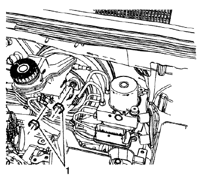
Fig. 19: Brake Master Cylinder And Nuts
- Remove the master cylinder nuts (1).
- Remove the brake master cylinder.
.gif)
Fig. 20: Master Cylinder Seal
- Remove the master cylinder seal (1).
- Inspect the master cylinder seal for damage or deterioration and replace, if necessary.
- Remove the brake fluid level indicator switch, if necessary. Refer to Brake Fluid Level Indicator Switch Replacement.
- Remove the master cylinder reservoir, if necessary. Refer to Master Cylinder Reservoir Replacement.
Installation Procedure
- Install the master cylinder reservoir, if removed. Refer to Master Cylinder Reservoir Replacement.
- Bench bleed the master cylinder. Refer to Master Cylinder Bench Bleeding.
- Install the brake fluid level indicator switch, if removed. Refer to Brake Fluid Level Indicator Switch Replacement.
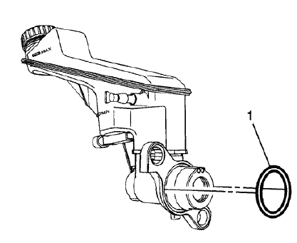
Fig. 21: Master Cylinder Seal
- Install the master cylinder seal (1).
- Install the master cylinder to the power vacuum brake booster.
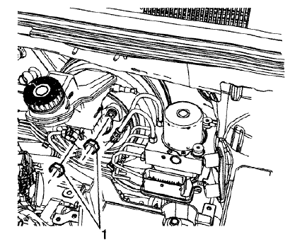
Fig. 22: Brake Master Cylinder And Nuts
CAUTION: Refer to Fastener Caution
- Install the master cylinder nuts (1) and tighten to 19 (14 lb ft).
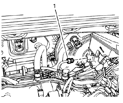
Fig. 23: Master Cylinder Primary Brake Pipe Fitting
- Connect the master cylinder primary brake pipe fitting (1) and tighten to 18 N.m (13 lb ft).
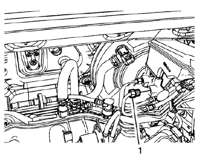
Fig. 24: Master Cylinder Outlet Port
- Connect the master cylinder secondary brake pipe fitting (1) and tighten to 18 N.m (13 lb ft).
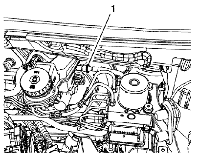
Fig. 25: Clutch Master Cylinder Reservoir Hose
- On manual transmission equipped vehicles, connect the clutch master cylinder reservoir hose (1).
- Connect the brake fluid level indicator switch electrical connector.
- Install the battery. Refer to Battery Replacement .
- Bleed the hydraulic brake system. Refer to Hydraulic Brake System Bleeding (Manual), Hydraulic Brake System Bleeding (Pressure).
READ NEXT:
 Master cylinder bench bleeding
Fig. 26: Depressing And Releasing Primary Piston
WARNING: Refer to Brake Fluid Irritant Warning .
CAUTION: Refer to Brake Fluid Effects on Paint and Electrical
Components
Caution .
Secure the mou
 Brake, accelerator, and clutch pedal replacement
Removal Procedure
Remove the battery tray. Refer to Battery Tray Replacement .
Fig. 29: Power Vacuum Brake Booster Bolts
Remove the power vacuum brake booster bolts (1).
Fig. 30: Brake Pedal
 Brake proportion valve replacement
Removal Procedure
WARNING: Refer to Brake Fluid Irritant Warning .
CAUTION: Refer to Brake Fluid Effects on Paint and Electrical
Components Caution .
Remove the battery. Refer to Battery Replacemen
SEE MORE:
 Front brake caliper bracket replacement
Removal Procedure
WARNING: Refer to Brake Dust Warning .
Raise and support the vehicle. Refer to Lifting and Jacking the Vehicle
.
Remove the tire and wheel assembly. Refer to Tire and Wheel Removal and
Installation .
Fig. 38: Upper And Lower Brake Caliper Guide Pin Bolts
NOTE:
DO NOT us
 DTC P182E OR P1915
Diagnostic Instructions
Perform the Diagnostic System Check - Vehicle prior to using this
diagnostic procedure.
Review Strategy Based Diagnosis for an overview of the diagnostic
approach.
Diagnostic Procedure Instructions provides an overview of each
diagnostic category.
DTC Descriptors
D
© 2019-2025 Copyright www.chevtrax.com

