Chevrolet Trax: Brake, accelerator, and clutch pedal replacement
Removal Procedure
- Remove the battery tray. Refer to Battery Tray Replacement .

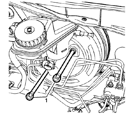
Fig. 29: Power Vacuum Brake Booster Bolts
- Remove the power vacuum brake booster bolts (1).

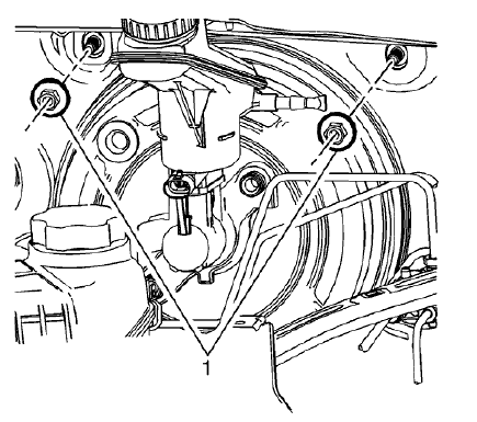
Fig. 30: Brake Pedal Assembly Upper Nuts
- Remove the brake pedal assembly upper nuts (1)

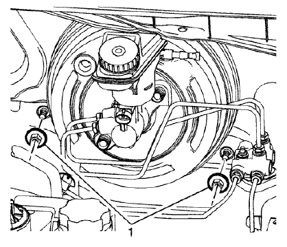
Fig. 31: Brake Pedal Assembly Lower Nuts
- Remove the brake pedal assembly lower nuts (1)
- Remove the steering column. Refer to Steering Column Replacement (Mexico, N40) , Steering Column Replacement (Canada, NJ1) , Steering Column Replacement (United States, NJ1) .
.gif)
Fig. 32: Brake Pedal Release Bracket Bolt
- Remove the brake pedal release bracket bolt (1).
.gif)
Fig. 33: Brake Pedal Release Bracket And Bolts
- Remove the brake pedal release bracket bolts (1).
.gif)
Fig. 34: Brake Pedal Release Bracket
- Remove the brake pedal release bracket (1).
- Remove the brake pedal position sensor. Refer to Brake Pedal Position Sensor Replacement .
- On manual transmission equipped vehicles, remove the clutch pedal position sensor. Refer to Clutch Pedal Position Sensor Replacement .
- Remove the accelerator pedal position sensor. Refer to Accelerator Pedal Position Sensor Replacement .
.gif)
Fig. 35: Clutch Master Cylinder Pushrod Locking Tabs
- On manual transmission equipped vehicles, compress the clutch master cylinder pushrod locking tabs (1) and release the clutch pedal by lifting the pedal upward.
.gif)
Fig. 36: Clutch Master Cylinder Bolts
- On manual transmission equipped vehicles, remove the clutch master cylinder bolts (1) and position the clutch master cylinder aside. Refer to Clutch Master Cylinder Replacement .
- Position aside any wiring harnesses attached to the brake pedal assembly bracket, as necessary.
.gif)
Fig. 37: Upper Brake Pedal Assembly Bolts
- Remove the 2 upper brake pedal assembly bolts (1).
.gif)
Fig. 38: Brake Pedal AssemblyAnd Dash Panel
- Pull the brake pedal assembly away from the dash panel.
- From behind the brake pedal assembly, remove the brake pedal assembly bracket nut (1).
.gif)
Fig. 39: Brake Pedal Assembly
- Remove the brake pedal assembly bracket (1).
- Remove the brake pedal assembly from the vehicle.
- Remove any necessary components from the brake pedal assembly.
Installation Procedure
- Install any removed components from the brake pedal assembly.
- Install the brake pedal assembly to the vehicle.
.gif)
Fig. 40: Brake Pedal Assembly
- Install the brake pedal assembly bracket (1).
.gif)
Fig. 41: Brake Pedal AssemblyAnd Dash Panel
- Pull the brake pedal assembly away from the dash panel.
CAUTION: Refer to Fastener Caution .
- From behind the brake pedal assembly, install the brake pedal assembly bracket nut (1) and tighten to 9 (80 lb in).
.gif)
Fig. 42: Brake Pedal Assembly Lower Nuts
- Install the brake pedal assembly lower nuts (1) and tighten to 19 N.m (14 lb ft).
.gif)
Fig. 43: Brake Pedal Assembly Upper Nuts
- Install the brake pedal assembly upper nuts (1) and tighten to 19 N.m (14 lb ft).
.gif)
Fig. 44: Upper Brake Pedal Assembly Bolts
- Install the 2 upper brake pedal assembly bolts (1) and tighten to 9 N.m (80 lb in).
- Reposition any wiring harnesses attached to the brake pedal assembly bracket, as necessary.
.gif)
Fig. 45: Clutch Master Cylinder Bolts
- On manual transmission equipped vehicles, install the clutch master cylinder and bolts (1). Refer to Clutch Master Cylinder Replacement .
.gif)
Fig. 46: Clutch Master Cylinder Pushrod Locking Tabs
- On manual transmission equipped vehicles, compress the clutch master cylinder pushrod locking tabs (1) and install the clutch pedal to the clutch master cylinder pushrod.
- Install the brake pedal position sensor. Refer to Brake Pedal Position Sensor Replacement .
- On manual transmission equipped vehicles, install the clutch pedal position sensor. Refer to Clutch Pedal Position Sensor Replacement .
- Install the accelerator pedal position sensor. Refer to Accelerator Pedal Position Sensor Replacement
.gif)
Fig. 47: Brake Pedal Release Bracket
- Install the brake pedal release bracket (1).
.gif)
Fig. 48: Brake Pedal Release Bracket And Bolts
- Install the brake pedal release bracket bolts (1) and tighten to 22 N.m (16 lb ft).
.gif)
Fig. 49: Brake Pedal Release Bracket Bolt
- Install the brake pedal release bracket bolt (1) and tighten to 22 N.m (16 lb ft).
- Connect the brake pedal position sensor electrical connector.
- Install the steering column. Refer to Steering Column Replacement (Mexico, N40) , Steering Column Replacement (Canada, NJ1) , Steering Column Replacement (United States, NJ1) .
.gif)
Fig. 50: Power Vacuum Brake Booster Bolts
- Install the power vacuum brake booster bolts (1) and tighten to 19 N.m (14 lb ft).
- Install the battery tray. Refer to Battery Tray Replacement .

