Chevrolet Trax: Master cylinder bench bleeding
Chevrolet Trax (2013-2022) Workshop Manual / Brakes / Hydraulic Brakes / Repair instructions / Master cylinder bench bleeding
.gif)
Fig. 26: Depressing And Releasing Primary Piston
WARNING: Refer to Brake Fluid Irritant Warning .
CAUTION: Refer to Brake Fluid Effects on Paint and Electrical Components Caution .
- Secure the mounting flange of the brake master cylinder in a bench vice so that the rear of the primary piston is accessible.
- Remove the master cylinder reservoir cap and diaphragm.
- Install suitable fittings to the master cylinder ports that match the type of flare seat required and also provide for hose attachment.
- Install transparent hoses to the fittings installed to the master cylinder ports, then route the hoses into the master cylinder reservoir.
- Fill the master cylinder reservoir to the maximum fill level with brake fluid from a clean, sealed brake fluid container. Refer to Master Cylinder Reservoir Filling.
- Ensure that the ends of the transparent hoses running into the master cylinder reservoir are fully submerged in the brake fluid.
- Using a smooth, round-ended tool, depress and release the primary piston
as far as it will travel, a depth
of about 25 mm (1 in), several times. Observe the flow of fluid coming from
the ports.
As air is bled from the primary and secondary pistons, the effort required to depress the primary piston will increase and the amount of travel will decrease.
- Continue to depress and release the primary piston until fluid flows freely from the ports with no evidence of air bubbles.
- Remove the transparent hoses from the master cylinder reservoir.
- Install the master cylinder reservoir cap and diaphragm.
- Remove the fittings with the transparent hoses from the master cylinder ports. Wrap the master cylinder with a clean shop cloth to prevent brake fluid spills.
- Remove the master cylinder from the vice.
BRAKE FLUID LEVEL INDICATOR SWITCH REPLACEMENT
Removal Procedure
- Disconnect the brake fluid level indicator switch electrical connector.
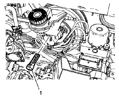
Fig. 27: Brake Fluid Level Indicator Switch
- Using a small, flat-bladed tool, lift the locking tab on the underside of the brake fluid level indicator switch (1) and remove the switch.
- Inspect the master cylinder reservoir for damage and replace, if necessary. Refer to Master Cylinder Reservoir Replacement.
Installation Procedure
- Install the master cylinder reservoir, if removed. Refer to Master Cylinder Reservoir Replacement.
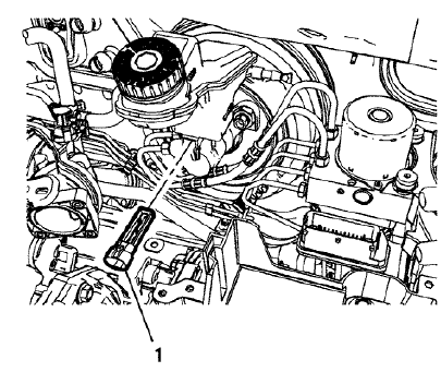
Fig. 28: Brake Fluid Level Indicator Switch
- Install the brake fluid level indicator switch (1) by pressing the switch firmly into the brake master cylinder reservoir.
- Connect the brake fluid level indicator switch electrical connector.
READ NEXT:
 Brake, accelerator, and clutch pedal replacement
Removal Procedure
Remove the battery tray. Refer to Battery Tray Replacement .
Fig. 29: Power Vacuum Brake Booster Bolts
Remove the power vacuum brake booster bolts (1).
Fig. 30: Brake Pedal
Brake proportion valve replacement
Removal Procedure
WARNING: Refer to Brake Fluid Irritant Warning .
CAUTION: Refer to Brake Fluid Effects on Paint and Electrical
Components Caution .
Remove the battery. Refer to Battery Replacemen
Brake pressure modulator valve front pipe replacement
Removal Procedure
WARNING: Refer to Brake Fluid Irritant Warning .
CAUTION: Refer to Brake Fluid Effects on Paint and Electrical
Components Caution
Remove the battery. Refer to Battery Replacement
SEE MORE:
How to Add Coolant to the
Coolant Surge Tank
Caution
This vehicle has a specific
coolant fill procedure. Failure to
follow this procedure could cause
the engine to overheat and be
severely damaged.
If no problem is found, check to see
if coolant is visible in the coolant
surge tank. If coolant is visible but
the coolant level is not at the
ind
Clock
Radio without Touchscreen
The infotainment system controls
are used to access the time and
date settings through the menu
system. See Operation
for information about how to use the
menu system.
Setting the Time and Date
Press .
Select Set Time or Set Date.
Turn the MENU/TUNE knob to
the desire
© 2019-2025 Copyright www.chevtrax.com
